Advertisement
Quick Links
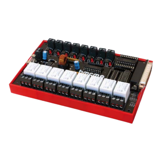
OR8/R8
Optocoupler/Relay cards
Connect digital signals.
Quite simple.
The optocoupler and relay boards OR8 and R8
are ideal to monitor and control digital states. The
digital inputs and outputs can be connected di-
rectly via a screw-clamp connection.
8 optocoupler inputs (OR8).
8 relay outputs (OR8, R8).
The eight optocouplers on the OR8 convert digi-
tal inputs in the voltage range of 5..30V into TTL
signals. Via relays, the OR8 and R8 switch eight
control lines (TTL) with up to 6A.
Clearly safe.
Due to the galvanic isolation of the channels from
each other and from the data acquisition and con-
trol system, the whole system is perfectly pro-
tected.
Current states.
Eight LEDs each dedicated to the inputs and out-
puts signalize if a channel is high or low.
Functional diagram
Well supplied.
The R8 is operated with 5V. The OR8 is powered
with 9-40V but can also be configured to 5V sup-
ply. The supply voltage is also connected via
screw-clamp terminals.
DIN rail mounting.
The optocoupler and relay boards are suitable for
DIN rail mounting. A DIN rail carrier (ZU-EW)
with bracket is already included with the delivery
of the OR8. It can be ordered as accessory for the
R8.
Compatibility.
Particularly simple is the connection to the digital
I/O interface USB-PIO as only a 25-pin D-Sub
extension cable is needed for connecting.
Advertisement

Summary of Contents for Omni bmcm OR8
- Page 1 OR8/R8 Optocoupler/Relay cards Connect digital signals. Quite simple. The optocoupler and relay boards OR8 and R8 are ideal to monitor and control digital states. The digital inputs and outputs can be connected di- rectly via a screw-clamp connection. Well supplied. 8 optocoupler inputs (OR8).
- Page 2 OR8/R8 Connections and pin assignments The available connections and different components of the R8 and OR8 boards are shown in the following figure of the board (view on top of the board (fitted with components), Sub-D connector on the right). Power supply The R8 is supplied with 5V DC at the screw-clamp terminal, the OR8 can be operated with 9..40V as well as with 5V (factory setting: 9..45V, jumper o-...
- Page 3 OR8/R8 Digital lines 1.4.1 As delivered, the OR8 is configured as follows: • port A (bit 0..7) = outputs (relays 1..8) • port B (bit 0..7) = inputs (optocouplers 1..8) Pin assignment and direction of the digital lines at the D-Sub25 male connector of the OR8 can be defined by the user.
- Page 4 OR8/R8 1.4.2 Pin assignment and direction of the digital lines at the 25-pin D-Sub male connector of the R8 are hard-wired. The control lines (TTL) for the individual relay output channels OUT 1..OUT8 of an R8 have to be ap- plied to channels 1-8.
Need help?
Do you have a question about the bmcm OR8 and is the answer not in the manual?
Questions and answers