Table of Contents
Advertisement
Quick Links
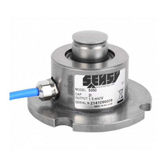
5950 LOAD CELL SERIES
1. GENERAL INFORMATION ......................................................................................................................................................................................... 2
1.1. Placement at level .............................................................................................................................................................................................. 2
1.2. Shocks, vibrations and overloads ....................................................................................................................................................................... 2
1.3. Electrical weldings .............................................................................................................................................................................................. 2
1.4. Lightning ............................................................................................................................................................................................................. 2
1.5. Exterior mechanical influences ........................................................................................................................................................................... 3
1.6. Setting of the counter force ................................................................................................................................................................................ 3
2. CABLing ...................................................................................................................................................................................................................... 3
2.1. Cable .................................................................................................................................................................................................................. 3
2.2. Wiring .................................................................................................................................................................................................................. 4
2.3. Parallel wiring ..................................................................................................................................................................................................... 4
2.4. Calibration........................................................................................................................................................................................................... 4
2.5. Measurement errors ........................................................................................................................................................................................... 5
2.6. Insulation test...................................................................................................................................................................................................... 5
2.7. Output impedance .............................................................................................................................................................................................. 6
2.8. Input impedance ................................................................................................................................................................................................. 6
3. MOUNTING WITH EASY MOUNT .............................................................................................................................................................................. 7
3.1. Mounting with 3 load cells .................................................................................................................................................................................. 7
3.2. Mounting with more than 3 loadcells: ................................................................................................................................................................. 7
4. example of mounting without easy mount ................................................................................................................................................................... 8
4.1. Mounting with a rubber foot (F5950) .................................................................................................................................................................. 8
4.2. Mounting with a solid steel base (A5950) ........................................................................................................................................................... 8
5. USE IN POTENTIALLY EXPLOSIVE ATMOSPHERE (OPTION) .............................................................................................................................. 9
5.1. Intrinsic safety protection .................................................................................................................................................................................... 9
6. Periodic inspections ..................................................................................................................................................................................................... 9
7. Use features .............................................................................................................................................................................................................. 10
8. Guarantee .................................................................................................................................................................................................................. 10
9. DRAWINGS AND WIRING DIAGRAMS ................................................................................................................................................................... 10
10. EU Declaration of Conformity .................................................................................................................................................................................. 15
MA-5950_EN.doc
INSTALLATION MANUAL
Page 1 on 15
Rev: 29-03-19
Advertisement
Table of Contents

Summary of Contents for SENSY 5950 Series
-
Page 1: Table Of Contents
5950 LOAD CELL SERIES INSTALLATION MANUAL 1. GENERAL INFORMATION ......................................2 1.1. Placement at level ......................................2 1.2. Shocks, vibrations and overloads ..................................2 1.3. Electrical weldings ......................................2 1.4. Lightning ..........................................2 1.5. Exterior mechanical influences ................................... 3 1.6. Setting of the counter force ....................................3 2. -
Page 2: General Information
Rev. Date Reason 29/03/2019 Adding points : 5, 6 ,7, 8, 9 and 10-EU Declaration of conformity 1. GENERAL INFORMATION 1.1. Placement at level This operation guarantees a good distribution of the loads and the uprightness of the effort. Make sure you check the placement at level of the sensors and of the supporting parts. -
Page 3: Exterior Mechanical Influences
1.5. Exterior mechanical influences In order to avoid measurement errors, the load to be weighed must not be subject to parasitic contributions: if there are any connecting pipes, cables and balls or draw- bolts, they must be installed with THE GREATEST FLEXIBILITY. -
Page 4: Wiring
Soldered connections have to be applied in the junction box, (preferably screwed connections). It is advised to place a bag of SILICA GEL to keep dry inside the junction box. SENSY could provide PVC junction box with a PG9 packing-gland, which could receive 4 or 6 parallel cells. -
Page 5: Measurement Errors
Electrically, the connections must be securing, the junction boxes exempt from humidity and the cables intact. If there is no fault to be seen, it is necessary to verify the internal circuit. SENSY can help to diagnose based on the associated diagnosis sheet provided in the appendix and filled in beforehand. 2.6. -
Page 6: Output Impedance
2.7. Output impedance The Wheatstone bridge is made up of 350 Ω gauges. At the output signal (OUT+: green, OUT-: white), the resistance is 700 Ω ± 5 Ω. This impedance must be in accordance with the individual cell data sheet, which could easily be determined with a multimeter. If a wider varying resistance is read, it means that there is a break-off or a short circuit current a resistance variation of several ohms would instead be a consequence of a severe overvoltage problem. -
Page 7: Mounting With Easy Mount
3. MOUNTING WITH EASY MOUNT The EASY MOUNT incorporates the fixing plates, the support parts, the counter force and the anti-rotation (displacement) in one direction. This kit with ball joint absorbs forces of up to 20 kN in the direction X and leaves enough freedom of movement in the direction Z for dilatations. CAUTION: this kit of assembly does not rigidify the assembly overall and does not allow to catch up possible buckling of foot. -
Page 8: Example Of Mounting Without Easy Mount
4. EXAMPLE OF MOUNTING WITHOUT EASY MOUNT 4.1. Mounting with a rubber foot (F5950) This mounting allows the sensor to be put straight on a levelled ground. The rubber allows to absorb the shocks and the slights irregularities of the state of the ground surface. 4.2. -
Page 9: Use In Potentially Explosive Atmosphere (Option)
Use of sensors in hazardous zones can only be done with Ex marked sensors, delivered with one or more of the certificates hereunder: ATEX: ISSeP07ATEX012X SENSY’s load cells which are marked Ex i comply with the following standards: ATEX EN 60079-0: 2012 EN 60079-26: 2007 EN 60079-11: 2012 The use of junction boxes or additional cable lengths must be considered in the choice of protection. -
Page 10: Use Features
The manufacturer’s guarantee is applicable as far as mounting recommendations and general use principle, like above described, are respected. For any particular use, not described in this document, it is mandatory to obtain a prior written agreement from SENSY S.A. for the validity of the guarantee. - Page 11 · Ref. Item Capacities ØA ØE Max. Deflexion (mm) Weight (kg) 5950-A 0.3 - 5 t 54.5 38.5 62.9 0.04 - 0.07 ±1.4 5950-B 7.5 - 15 t 38.5 62.9 0.08 - 0.15 ±1.4 5950-C 20 t 38.5 62.9 ±1.4 Other capacities and dimensions available on request Dimensions in mm Wiring...
- Page 12 Ref. Item* Capacities P N/mm² Weight (kg) A5950-AB 0.3 - 15 t ± 120 (15 t) ± 0.76 A5950-C 20 t ± 100 ± 0.95 *Material: stainless steel Other capacities and dimensions available on request Dimensions in mm Other view...
- Page 13 Electrical ground strap ACCESS-I595x-SEM Ref. Item* Capacities I595x-A 0.3 - 20 t *x=Material: I5950 - stainless steel; I5955 - alloy steel Other capacities and dimensions available on request Dimensions in mm Other views...
- Page 14 Electrical ground strap · Ref. Item* Capacities M595x-A 0.3 - 20 t *Material: M5950 - stainless steel; M5955 - alloy steel Other capacities and dimensions available on request Dimensions in mm Other view...
-
Page 15: Eu Declaration Of Conformity
CONCERNED ITEMS: 5950, see calibration certificate related to model and serial number. SENSY S.A. certify that the items described here above have been duly designed, manufactured and tested for use in accordance with the essential requirements defined in the European Directives listed here under.
Need help?
Do you have a question about the 5950 Series and is the answer not in the manual?
Questions and answers