Advertisement
Table of Contents
- 1 Table of Contents
- 2 Warranty Information
- 3 Specifications
- 4 Product Description
- 5 Disassembly/Assembly Procedures
- 6 Test Procedures
- 7 Series III Test Setup Diagram
- 8 Part List Notes
- 9 Main Part List, Acoustimass 5 Series III (See Figure 2)
- 10 Packing List, Acoustimass 5 Series III Loudspeaker System (See Figure 3)
- 11 Part List, Acoustimass 5 Series III Loudspeaker System Crossover (See Figure 4)
- Download this manual
Advertisement
Table of Contents

Related Manuals for Bose Acoustimass 5 Series


Summary of Contents for Bose Acoustimass 5 Series
- Page 1 ® ® ® Acoustimass 5 Series III Loudspeaker System Service Manual © 1998 Bose Corporation Part Number 198662 Rev. 00...
-
Page 2: Table Of Contents
Packing List, Acoustimass 5 Series III Loudspeaker System (see Figure 3) ......7 Figure 3. Acoustimass 5 Series III Loudspeaker System Packing View .......... 7 Part List, Acoustimass 5 Series III Loudspeaker System Crossover (see Figure 4) ....8 Figure 4. Acoustimass 5 Series III Loudspeaker System Crossover Layout Diagram ....8 Figure 5. -
Page 3: Specifications
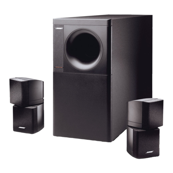
10-200 Watts per channel. PRODUCT DESCRIPTION ® ® The Bose Acoustimass 5 Series III Loudspeaker System offers several improvements over the Series II. It uses two extended response satellite speakers that are 20 percent smaller than earlier versions. The satellite speaker assemblies reproduce the middle and high frequencies of two full-range channels. -
Page 4: Disassembly/Assembly Procedures
DISASSEMBLY/ASSEMBLY PROCEDURES Note: Refer to Figure 2 for the following 4.2 Slide the crossover assembly onto the procedures. tabs located on the terminal cap (7). 1. Terminal Cap Removal 4.3 Replace the four screws (9) removed in procedure 3.2. 1.1 Using a phillips-head screwdriver, remove the six screws (4) that secure the 4.4 Perform procedure 2. -
Page 5: Test Procedures
Replace any satellite assembly that the channels. buzzes or sounds distorted. Note: The Acoustimass 5 Series III satellite 2.3 The sound output level should drop by assemblies are non-repairable. If you have approximately half. If the sound output level... -
Page 6: Part List Notes
PART LIST NOTES 1. This part is not normally available from Customer Service. Approval from the Field Service Manager is required before ordering. 2. The individual parts located on the PCBs are listed in the Electrical Part List. MAIN PART LIST ®... -
Page 8: Packing List, Acoustimass 5 Series Iii Loudspeaker System (See Figure 3)
PACKING LIST ® Acoustimass 5 Series III Loudspeaker System (see Figure 3) Item Description Part Number Q t y . Note Number PACKING, CORNER, POST, BASS INSRT 148364 PACKING, CORNER, POST, BASS MOD 148044 SATELLITE ASSY, SGL, BLK 192420-019 SATELLITE ASSY, SGL, WHT 192420-029 BAG, POLY, 13.5x35x9.5x2.5 mil 114522... -
Page 9: Part List, Acoustimass 5 Series Iii Loudspeaker System Crossover (See Figure 4)
PART LIST ® Acoustimass 5 Series III Loudspeaker System Crossover (see Figure 4) Reference Description Part Number Qty. Note Designator R1, 2 39 Ohm, WW, 5W 132105-390 R3, 4 5.1 Ohm, WW, 5W, 10% 132105-5R1 C1, 2 47 uF, EL, BP, 85, 50V, 20% 136548 C3, 4 15 uF, EL, BP, 85, 50V, 20%... - Page 10 1.5A 15uF PTC1 INL+ OUTL+ 47uF LEFT CHANNEL INL- OUTL- 1.5A 15uF PTC2 INR+ OUTR+ 47uF RIGHT CHANNEL INR- OUTR- NOTES: UNLESS OTHERWISE SPECIFIED 1. RESISTOR VALUES ARE IN OHMS. 2. CAPACITOR VALUES ARE IN MICROFARADS. 3. INDUCTOR VALUES ARE IN MICROHENRIES. Figure 5.
Need help?
Do you have a question about the Acoustimass 5 Series and is the answer not in the manual?
Questions and answers