
Summary of Contents for CYP CPLUS-V8H8HPA
- Page 1 CPLUS-V8H8HPA 8x8 Matrix with Audio Output Operation Manual Operation Manual...
- Page 3 DISCLAIMERS The information in this manual has been carefully checked and is believed to be accurate. Cypress Technology assumes no responsibility for any infringements of patents or other rights of third parties which may result from its use. Cypress Technology assumes no responsibility for any inaccuracies that may be contained in this document.
- Page 4 SAFETY PRECAUTIONS Please read all instructions before attempting to unpack, install or operate this equipment and before connecting the power supply. Please keep the following in mind as you unpack and install this equipment: • Always follow basic safety precautions to reduce the risk of fire, electrical shock and injury to persons.
-
Page 5: Table Of Contents
CONTENTS 1. Introduction ............1 2. Applications .............1 3. Package Contents ..........1 4. System Requirements ........2 5. Features ............2 6. Operation Controls and Functions ....3 6.1 Front Panel ..........3 6.2 Rear Panel ..........5 6.3 Remote Control ......... 6 6.4 IR Cable Pinouts ........7 6.5 RS-232 Pinout and Defaults ...... -
Page 6: Introduction
1. INTRODUCTION This 4K UHD 8×8 HDMI Matrix provides the ability to connect up to eight 4K UHD HDMI sources to up to eight 4K UHD HDMI displays and freely switch between them. This unit comes with full support for 18Gbps resolutions up to, and including 4K@60Hz (4:4:4, 8-bit) as well as support for 16-bit Deep Color, HDR (High Dynamic Range), HD audio and other features defined by the HDMI 2.0 specification. -
Page 7: System Requirements
4. SYSTEM REQUIREMENTS • HDMI source equipment such as media players, video game consoles or set-top boxes. • HDMI receiving equipment such as HDTVs, monitors or audio amplifiers. • The use of Premium High Speed HDMI cables is highly recommended. 5. -
Page 8: Operation Controls And Functions
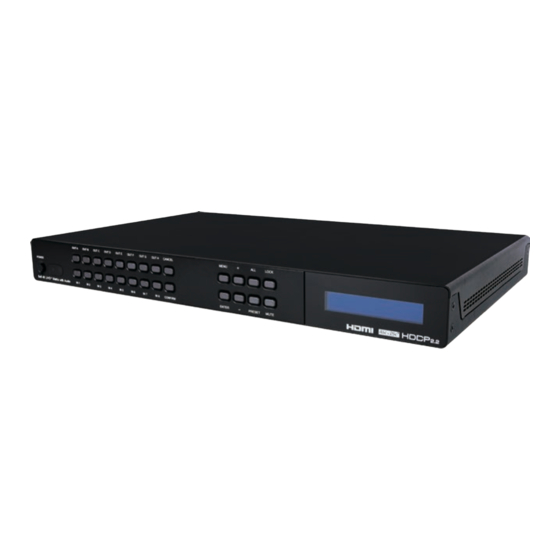
6. OPERATION CONTROLS AND FUNCTIONS 6.1 Front Panel OUT A OUT B OUT C OUT D OUT E OUT F OUT G OUT H CANCEL MENU LOCK POWER 8x8 4K UHD + Matrix with Audio IN 1 IN 2 IN 3 IN 4 IN 5 IN 6... - Page 9 ENTER Button: Press to confirm a selection within the LCD menu or to go deeper into a menu item. + (PLUS) & - (MINUS) Buttons: Press to move up and down or adjust selections within the LCD menu. ALL Button: Press this button to select all outputs simultaneously for routing.
-
Page 10: Rear Panel
6.2 Rear Panel AUDIO OUT IR IN CONTROL RS232 SERVICE DC 24V HDMI IN HDMI OUT HDMI IN 1~8 Ports: Connect to HDMI source equipment such as media players, game consoles or set-top boxes. HDMI OUT A~H Ports: Connect to HDMI TVs, monitors, or amplifiers for digital video and audio output. -
Page 11: Remote Control
6.3 Remote Control POWER Button: Press to power the unit on or place it into stand-by mode. 1 / A 5 / E INFO 2 / B 6 / F MUTE 1/A ~ 8/H Buttons: Press these keys to configure PRESET 3 / C 7 / G... -
Page 12: Ir Cable Pinouts
6.4 IR Cable Pinouts IR Extender Cable Infrared Power Ground 6.5 RS-232 Pinout and Defaults Serial Port Default Settings Baud Rate 19200 Data Bits DE-9 Female Port Parity Bits None Stop Bits Flow Control None... -
Page 13: Front Panel Lcd Menu
6.6 Front Panel LCD Menu All primary functions of this unit can be controlled by using the front panel LCD menu which is activated by pressing the MENU button on the front of the unit. Use the + (PLUS), − (MINUS), and ENTER buttons to navigate the LCD menu. - Page 14 VIDEO SETUP 2ND LEVEL 3RD LEVEL 4TH LEVEL 5TH LEVEL ALL MODE EDID Mode Appoint Mode FHD 2CH FHD MCh UHD 2Ch UHD MCh Appoint Mode IN1 ~ IN8 EDID UHD+ 2Ch UHD+ MCh User 1~8 EDID Setup Sink A~H FHD 2CH FHD MCh UHD 2Ch...
- Page 15 ■ Appoint Mode EDID: Select the EDID to be used by each input when Appoint Mode is active. ■ All Mode EDID: Select the EDID to be used by all inputs when All Mode is active. 2) Preset Setup: Use the “+”/“-”keys to select a preset number then press the “Enter”...
- Page 16 SYSTEM SETUP 2ND LEVEL 3RD LEVEL 4TH LEVEL Firmware [Info Display] Firmware Update Do USB Update? Factory Reset Do Factory Reset? STANDARD MODE Keypad Action Mode User Mode Y (SHOW) Show Timing Info A ~ H N (Don’t Show) 1) Firmware: Displays the unit’s current firmware version. 2) Firmware Update: Provides a way to update the unit’s firmware.
- Page 17 NETWORK STATUS 2ND LEVEL 3RD LEVEL Link: [Current link status] Mode: [Current network mode] [Current IP address] Mask: [Current netmask] Gate: [Current gateway address] MAC: [MAC address] 1) Network Status: Displays the unit’s current networking information or status for each item. NETWORK SETUP 2ND LEVEL 3RD LEVEL...
- Page 18 4) Gate: When DHCP is off, the gateway address can be set here. Press the “Enter” button to begin editing the address and use the “+” and “-” buttons to adjust each value. Press the “Enter” button to store the current number segment and move to the next segment.
-
Page 19: Webgui Control
6.7 WebGUI Control • Device Discovery Please obtain the “Device Discovery” software from your authorized dealer and save it in a directory where you can easily find it. Connect the unit and your PC/Laptop to the same active network and execute the “Device Discovery” software. Click on “Find Devices on Network”... - Page 20 • WebGUI Overview After connecting to the WebGUI’s address in a web browser, the login screen will appear. Please enter the appropriate user name and password then click “Submit” to log in. Note: The default user name and password is “admin”. On the left side of the browser you will see the following menu tabs where all primary functions of the unit are controllable via the built in WebGUI.
-
Page 21: Video Switch Tab
6.7.1 Video Switch Tab This page provides video routing settings, preset saving/loading, and I/O renaming options. To begin assigning a new video route, please click the button of the HDMI output you wish to send video to and then click on the button of the preferred HDMI input port. If desired, you may select more than one output prior to selecting the input. - Page 22 3) Output Edit: A variety of output settings, including name, muting, test pattern configuration, downscaling, and OSD options can be configured here. Please click the “Edit” icon ( ) within the Output button to open up the Output Edit window. ■...
- Page 23 ■ Downscaling: This switch enables or disables the downscaling functionality of the output. When this setting is turned on, 4K sources will be automatically downscaled to 1080p while maintaining the original framerate. ■ OSD: This switch enables or disables the custom text display for this output.
- Page 24 ■ Set Input Name: To rename the input port, type the new name in the space provided in the Edit window. Click the “Save” button to confirm the change. Note: Blank spaces (“ ”) are not allowed in names. ■ HDCP: Provides control over the HDCP behavior of each HDMI input.
-
Page 25: Edid Settings Tab
at this stage by selecting the “Edit” icon ( ). Click the center of the preset’s button to store the current routing state in that preset. ■ Recall Preset: When you wish to load a previously stored preset, please click the “Recall” icon ( ) and you will be presented with a choice of the 8 available presets. - Page 26 ■ Download: To save an existing user EDID to your local PC please press the “Download” button next to the EDID you would like to save. Depending on your browser settings you will either be asked where to save the downloaded file, or the file will be transferred directly to the default download location on your ■...
-
Page 27: Device Settings Tab
This matrix provides the following 6 default EDIDs: Unit’s Default EDIDs FHD/2CH 1920×1080p@60Hz (4.95Gbps) & 8-bit color, LPCM FHD/MCH 1920×1080p@60Hz (4.95Gbps) & 8-bit color, LPCM 7.1 & Bitstream UHD/2CH 3840×2160p@30Hz (10.2Gbps) & Deep Color (8/10/12-bit), LPCM 2.0 UHD/MCH 3840×2160p@30Hz (10.2Gbps) & Deep Color (8/10/12-bit), LPCM 7.1 &... -
Page 28: User Config Tab
2) IR Discrete Custom Code: Allows setting the discrete IR code prefix, primarily for use with learning remotes, to control the functions of this matrix. Note: To obtain a complete list of IR control codes please contact your authorized dealer. 3) Temperature &... -
Page 29: System Settings Tab
6.7.5 System Settings Tab This tab provides system information, power control, Ethernet configuration options, system configuration backup/restore, and firmware update functions. 1) Power: Press this switch to toggle the unit’s power between ON and OFF (standby mode). Note: While in standby mode the unit’s WebGUI, Telnet and RS-232 controls are still active. -
Page 30: Telnet Control
to locate the saved XML file, then click the “Restore” button. 5) Reset to Default: Press this button to reset the unit to its factory default state. After the reset is complete, the unit will reboot automatically. 6) Firmware Upgrade: To update the unit’s firmware, click the “Choose File”... -
Page 31: Serial And Telnet Commands
6.9 Serial and Telnet Commands COMMAND Description and Parameters General & System Commands HELP Show the full command list. ? Show the full command list. SET FACTORY DEFAULT Reset the unit to the factory defaults. SET FACTORY IPCONFIG DEFAULT Reset the unit’s network settings to the factory defaults. SET FACTORY OUT ROUTE DEFAULT... - Page 32 COMMAND Description and Parameters GET UART 1 BAUDRATE Show the current baud rate of the RS-232 port. SET IR IN CHANNEL N1 Set the channel for the IR input to use. N1 = 0~15 [IR Channel] GET IR IN CHANNEL Show the current channel used by the IR input.
- Page 33 COMMAND Description and Parameters SET KEYLOCK N1 Enable or disable the front panel key lock. Available values for N1: [Locked] [Unlocked] GET KEYLOCK Show the current front panel lock state. GET FW VER Show the unit’s current firmware version. SET OUT N1 OSD INFO DISPLAY N2 Enable or disable the info OSD for the specified output.
- Page 34 COMMAND Description and Parameters SET OUT ROUTE N1,N1,N1,... Set multiple input/output routes simultaneously. N1 = {A~H}{1~8} [Output and Input port pair] Note: Each routing pair consists of the output letter followed by the input number with no space between them. Additional routes are added by separating them with commas (without spaces).
- Page 35 COMMAND Description and Parameters SET OUT N1 MASK N2 Enable or disable the A/V mute setting on the specified output. N1 = A~H [Output Port] Available values for N2: [Mute A/V] [Unmute A/V] GET OUT N1 MASK Display the current A/V mute setting for the specified output. N1 = A~H [Output port] SET IN N1 NAME N2...
- Page 36 COMMAND Description and Parameters SET OUT N1 4K2K DOWNSCALE MODE N2 Enable/disable the 4K to 1080p downscale mode used by the specified output. N1 = A~H [Output port] Available values for N2: [Bypass mode] [Downscale 4K to 1080p] GET OUT N1 4K2K DOWNSCALE MODE Show the current 4K to 1080p downscale mode state.
- Page 37 COMMAND Description and Parameters SET PATTERN N1 TIMING N2 Set the test pattern’s resolution for the specified output. N1 = A~H [Output port] Available values for N2: [720p@60Hz] [1080p@60Hz] [720p@50Hz] [1080p@50Hz] [4K@25Hz] [4K@30Hz] [4K@50Hz] [4K@60Hz] GET PATTERN N1 TIMING Show the test pattern’s current resolution for the specified output. N1 = A~H [Output port] GET PATTERN TIMING LIST...
- Page 38 COMMAND Description and Parameters GET PATTERN N1 TYPE Show the current test pattern type used by the specified output. N1 = A~H [Output port] EDID Commands SET ALL IN EDID MODE N1 Select the EDID management mode to use (All or Appoint) for all inputs.
- Page 39 COMMAND Description and Parameters SET ALL IN EDID N1 Set the EDID to use when the “All” EDID mode is active. Available values for N1: [Internal 1] [Internal 2] [Internal 3] [Internal 4] [Internal 5] [Internal 6] [User 1] [User 2] [User 3] [User 4] [User 5]...
- Page 40 COMMAND Description and Parameters SET IN N1 EDID N2 Set the EDID to use on the specified input in “Appoint” mode. N1 = 1~8 [Input port] Available values for N2: [Internal 1] [Internal 2] [Internal 3] [Internal 4] [Internal 5] [Internal 6] [User 1] [User 2]...
- Page 41 COMMAND Description and Parameters SET EDID N1 NAME N2 Set the name for the specified EDID. N1 = 7~14 [EDID number] N2 = {EDID Name} [32 characters max] Note: Only User EDIDs may be renamed. GET EDID N1 NAME Show the name for the specified EDID. N1 = 1~22 [EDID Number] GET INTERNAL N1 EDID DATA...
- Page 42 COMMAND Description and Parameters HDCP Commands SET IN N1 HDCP MODE N2 Set the HDCP behavior of the specified input. N1 = 1~8 [Input port] Available values for N2: [HDCP Disabled] [Follow Source] [Follow Display] GET IN N1 HDCP MODE Show the current HDCP behavior used by the specified input.
- Page 43 COMMAND Description and Parameters GET IN N1 HDCP ABILITY Show the HDCP compliance level of the source connected to the specified input. N1 = 1~8 [Input port] Available result codes: [No HDCP] [HDCP 1.x] [HDCP 2.2] [HDCP 1.4+2.2] GET OUT N1 HDCP ABILITY Show the HDCP compliance level of the display device connect- ed to the specified output.
- Page 44 COMMAND Description and Parameters GET IPADDR Show the unit’s current IP address. SET NETMASK N1 Set the unit’s static netmask. N1 = X.X.X.X [X = 0 ~ 255] GET NETMASK Show the unit’s current netmask. SET GATEWAY N1 Set the unit’s static gateway address. N1 = X.X.X.X [X = 0 ~ 255] GET GATEWAY...
- Page 45 COMMAND Description and Parameters SET WEBGUI PASSWORD N1 Set the WebGUI “User” login password. N1 = {Password} [16 characters max] GET WEBGUI PASSWORD Show the current WebGUI “User” login password. Note: Commands will not be executed unless followed by a carriage return.
-
Page 46: Connection Diagram
7. CONNECTION DIAGRAM Blu-ray Players Set-top Boxes RS-232 Wireless Equipped HDMI Inputs Router PC/Laptop RS-232 AUDIO OUT Power Supply IR IN CONTROL RS232 SERVICE DC 24V HDMI IN HDMI OUT 60° Active 1 / A 5 / E INFO 2 / B 6 / F MUTE 3 / C... -
Page 47: Specifications
8. SPECIFICATIONS 8.1 Technical Specifications HDMI Bandwidth 18Gbps Input Ports 8×HDMI (Type-A) Output Ports 8×HDMI (Type-A) 8×Analog Stereo (3.5mm) Control Ports 1×RS-232 (DE-9) 1×Ethernet (RJ-45) 1×IR Extender (3.5mm) Service Port 1×USB 2.0 (Type A) IR Frequency 38kHz Baud Rate 19200 Power Supply 24V/3.75A DC (US/EU standards, CE/FCC/UL certified) -
Page 48: Video Specifications
8.2 Video Specifications Input Output Supported Resolutions (Hz) HDMI HDMI 720×400p@70/85 640×480p@60/72/75/85 720×480i@60 720×480p@60 720×576i@50 720×576p@50 800×600p@56/60/72/75/85 848×480p@60 1024×768p@60/70/75/85 1152×864p@75 1280×720p@50/60 ... -
Page 49: Audio Specifications
Input Output Supported Resolutions (Hz) HDMI HDMI 2560×1440p@60RB 2560×1600p@60RB 2048×1080p@24/25/30 2048×1080p@50/60 3840×2160p@24/25/30 3840×2160p@50/60 (4:2:0) 3840×2160p@24, HDR10 3840×2160p@50/60 (4:2:0),HDR10 3840×2160p@50/60 4096×2160p@24/25/30 4096×2160p@50/60 (4:2:0) ... -
Page 50: Analog Audio
8.3.2 Analog Audio Analog Output Max Audio Level 2Vrms THD+N < −60dB@0dBFS 1kHz (A-wt) > 105dB@0dBFS Frequency Response < ±3dB@20Hz~20kHz Crosstalk < −60dB@10kHz Impedance 470Ω Type Unbalanced 8.4 Cable Specifications 1080p 4K30 4K60 (4:4:4) (4:4:4) Cable Length 8-bit 12-bit 8-bit 8-bit High Speed HDMI Cable HDMI Input... -
Page 51: Acronyms
9. ACRONYMS ACRONYM COMPLETE TERM ASCII American Standard Code for Information Interchange Cat.5e Enhanced Category 5 cable Cat.6 Category 6 cable Cat.6A Augmented Category 6 cable Cat.7 Category 7 cable Consumer Electronics Control Command-Line Interface Digital-to-Analog Converter Decibel DHCP Dynamic Host Configuration Protocol Digital Visual Interface EDID Extended Display Identification Data... - Page 52 ACRONYM COMPLETE TERM Signal-to-Noise Ratio Transmission Control Protocol THD+N Total Harmonic Distortion plus Noise TMDS Transition-Minimized Differential Signaling Ultra-High-Definition (10.2Gbps) Ultra-High-Definition Plus (18Gbps) UHDTV Ultra-High-Definition Television Universal Serial Bus Video Graphics Array WUXGA (RB) Widescreen Ultra Extended Graphics Array (Reduced Blanking) Extended Graphics Array Ω...
- Page 56 CYPRESS TECHNOLOGY CO., LTD. www.cypress.com.tw...
Need help?
Do you have a question about the CPLUS-V8H8HPA and is the answer not in the manual?
Questions and answers