Advertisement
Available languages
Available languages
Quick Links
I
NSTALLATION AND
The illustrations in this document are generic; your control appearance may be slightly different from the ones shown.
Electrical wiring must be done by qualifi ed personnel in accordance with all applicable codes and standards.
Before connecting wires, unplug the unit or switch power off at service panel and lock service disconnecting means
to prevent power from being switched on accidentally. Always wear safety glasses and gloves while performing
these instructions.
INSTALLATION
Unplug the ventilation unit.
NOTE: If the control is to be installed in an electric box, go to step
Cut a 2
7
/
" x 1¾" hole in a wall, at a
8
convenient location for the control.
Route a cable (type 22/4) for the
control from the unit to this hole. See
figure at right.
Temporarily place the control over the
hole and mark both mounting screw
hole positions.
Remove the control, drill both screw
holes (3/16" Ø) in wall and insert the wall
anchors (included).
Strip the end of the cable to access the 4 wires (about 3"). Strip the
end of each wire (about 1/4"). Connect the wires to the terminals,
regardless of the wire color. Note which wire color has been
chosen for each terminal. See illustration below.
VC0233
Mount the control to the wall.
Depending on the type of fresh air system installed,
perform
the
electrical
connector of the unit as per one of the four models illustrated
hereafter. For more details, refer to the installation manual of
the ventilation unit.
NOTE: To avoid miswiring, refer to the notes taken at step
to match the wire color with the right terminal.
U
G
SER
UIDE FOR
READ AND SAVE THESE INSTRUCTIONS
Ø 3/16", typ.
VC0210A
12V
LED
OVR
Gnd
VC0211
connection
to
the
terminal
20-40-60 C
ONTROL
WARNING
!
Remote 6 & 7 positions terminals
.
VC0234
NOTE: The auxiliary wall control can be used with a 3-wire
connection by removing the LED signals. This optional
wiring will not allow an installation with more than
1 auxiliary wall control to properly synchronize their LEDs
on an event requested from a peer. Only the auxiliary wall
control having requested the timer event will have the
LEDs updated accordingly.
VC0238
Remote 4 & 6 positions terminals
VC0237
VC0239
Plug the ventilation unit and test the wall control.
HOW TO USE THE CONTROL
VC0190
(
.
PART NO
VBATHW
Remote 10 positions terminal
On-board terminal
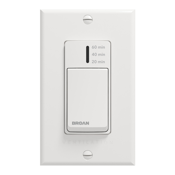
The main button works following this
sequence:
• Click 1 = 20 min
• Click 2 = 40 min
• Click 3 = 60 min
• Click 4 = OFF
• and so on
The indicator lights up as per the selected
duration and the system exchanges air at
MAX speed.
)
12V
LED
OVR
Gnd
23848 rev. 02
Advertisement

Related Manuals for Broan VBATHW

Summary of Contents for Broan VBATHW
- Page 1 NSTALLATION AND UIDE FOR ONTROL PART NO VBATHW READ AND SAVE THESE INSTRUCTIONS The illustrations in this document are generic; your control appearance may be slightly different from the ones shown. WARNING Electrical wiring must be done by qualifi ed personnel in accordance with all applicable codes and standards.
- Page 2 20-40-60 ( ANUAL DEL USUARIO Y DEL INSTALADOR PARA EL CONTROL DE PIEZA VBATHW LEA Y GUARDE ESTAS INSTRUCCIONES Las ilustraciones en este documento son generales; su control puede tener un aspecto ligeramente diferente. ADVERTENCIA El cableado eléctrico debe ser realizado por personal cualifi cado, de acuerdo con todos los códigos y normas aplicables.
Need help?
Do you have a question about the VBATHW and is the answer not in the manual?
Questions and answers