
Summary of Contents for thermital AF ACS B
- Page 1 ISTRUZIONI D’USO E D’INSTALLAZIONE OPERATING AND INSTALLATION INSTRUCTIONS AF ACS B AF ACS 220 B AF ACS 300 B EMIX TANK 220 EMIX TANK 300...
- Page 2 Indice Generalità Introduzione Dati di targa Installare AF ACS Collegamenti elettrici Come utilizzare e configurare le resistenze elettriche Pannello utente frontale Scollegare e disinstallare AF ACS Collegare AF ACS ad un impianto solare termico Gamma e confomità MODELLO CODICE AF ACS 220 B 20112951 AF ACS 300 B 20112952...
- Page 3 IMPORTANTE! Leggere prima di iniziare l’installazione Questo sistema deve seguire rigidi standard di sicurezza e di funzionamento. Per l’installatore o il personale di assistenza è molto importante installare o riparare il sistema di modo che quest’ultimo operi con sicurezza ed efficienza. Per un’installazione sicura e un buon funzionamento è...
- Page 4 Luogo d’installazione Si raccomanda di far installare questo apparecchio da un tecnico qualificato seguendo le istruzioni di installazione allegate. AVVERTIMENTO Non installare questo apparecchio dove ci sono fumi, gas infiammabili o molta umidità, come in una serra. Non installare l’unità dove ci sono apparecchiature che generano un calore eccessivo. Non installare l’unità...
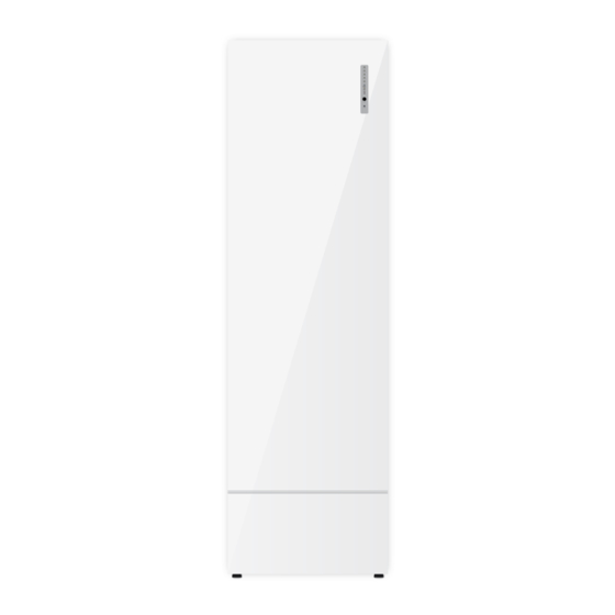
- Page 5 Introduzione AF ACS B è l’innovativa unità interna, in grado di fornire acqua calda ad uso sanitario da fonte termodinamica, in tutte le stagioni dell’anno, cioè indipendentemente dal modo di funzionamento del sistema di climatizzazione/riscaldamento. AF ACS B è un componente che si aggiunge alla gamma già molto ampia di unità interne.
- Page 6 Lo schema seguente illustra il concetto esposto sopra ed evidenzia una configurazione di sistema in cui coesistono tre unità interne ad espansione diretta, un hydrokit per un impianto a pavimento ed un AF ACS B, tutti collegati ad una AFEX 110.
- Page 7 Come installare AF ACS B AF ACS B può funzionare solo con unità esterna della gamma AFEX; In condizioni di emergenza, AF ACS B può essere utilizzato come un bollitore elettrico senza la pompa di calore AFEX. Prima di tutto è necessario rimuovere la copertura inferiore; non è fissata con viti o altro, basta estrarla dal basamento.
- Page 8 R410A 3/8” IN è la tubazione dall’unità esterna R410A 3/8” OUT è la tubazione verso l’unità esterna E’ necessario prestare la massima attenzione al rispetto delle connessioni, sia che AF ACS B venga collegato alla porta EMX sia che venga collegato alla porta refrigerante standard.
- Page 9 ACQUA CALDA 38°-65° C L’installazione del vaso di espansione è rac- comandata per prevenire problemi idraulici all’unità AF ACS B. Per l’installazione seguire la seguente procedura: 1. Rimuovere il tappo in plastica 2. Installare un rubinetto di intercettazione per scaricare l’acqua dal circuito (in caso di necessità)
- Page 10 Limiti di collegamento Circuito frigorifero AF ACS B è un componente che si può collegare contemporaneamente alle altre tipologie di unità interna senza spe- cifiche limitazioni, sfruttando l’apposita connessione frigorifera per AF ACS B e tenendo in debito conto la lunghezza delle tubazioni di AF ACS B da sommare alla lunghezza totale prevista dall’unità...
- Page 11 MASSIMO DISLIVELLO TRA UNITÀ INTERNE: Selezionare l’applicazione/configurazione in base al numero di unità interne e al modello di unità esterna. Verificare che la lunghezza totale delle tubazioni (inclusa la tubazione di AF ACS B) non ecceda le distanze massime indicate in tabella.
- Page 12 Alimentazione generale AF ACS B deve sempre essere collegato all’alimentazione elettrica in modo separato rispetto alla connessione dell’uni- tà esterna, alla quale sono connessi con il solo cavo schermato del bus di comunicazione a due fili come tutte le altre unità...
- Page 13 ON/OFF Se AF ACS B è alimentato in monofase, è necessario collegare la sola linea L1. Se è necessario l’utilizzo del secondo e terzo step di resistenze elettriche integrative, ponticellare i morsetti L1-L2 e L2-L3. Per il settaggio delle resistenze integrative riferirsi alla sezione dedicata.
- Page 14 Cavo elettrico bipolare schermato. Le dimensioni e la lunghezza del cavo elettrico consigliato sono indicate nelle istru- zioni per l’installazione dell’unità esterna (considerare il serbatoio AF ACS B come unità interna). Le caratteristiche del cavo non devono essere inferiori a quelle del modello H05VVC4V5-K (secondo la norma CEI 20-20 CENELEC HD21).
- Page 15 Selezione tipo di applicazione: JP1 CHIUSO: collegare l’unità alla porta AF ACS (quando il serbatoio AF ACS B è parte di un sistema). JP1 APERTO: collegare l’unità alla porta del refrigerante sull’unità esterna (se non vi è alcuna porta speciale).
- Page 16 SETTAGGIO SWITCH (SCHEDA DI CONTROLLO) ATTENZIONE ! Togliere l’alimentazione al sistema prima di modificare il settaggio. SW1: SETTAGGIO DELLE RESISTENZE ELETTRICHE DI BACKUP. Vedere sezione “Utilizzo delle resistenze elettriche”. SW2: SETTAGGIO DEL VOLUME DEL BOLLITORE. Impostare SW2 per scegliere il volume del bollitore: OFF - OFF = 300 l ON - OFF = 220 l IMPOSTAZIONE DI FABBRICA...
- Page 17 Come utilizzare e configurare le resistenze elettriche Per configurare la modalità di utilizzo delle resistenze elettriche, una volta che AF ACS è acceso ed attivo, bisogna tenere premuto il tasto nero fino all’accensione del led blu. Il led blu acceso segnala che una resistenza elettrica è in funzione.
- Page 18 Collegamento AF ACS B- Solo applicazioni ACS AF ACS B può essere utilizzato con le unità esterne AFEX in una specifica configurazione allo scopo di creare un siste- ma a pompa di calore solo per la produzione di ACS. Solo applicazione ACS Collegare l’unità...
- Page 19 Pannello utente frontale Il pannello di controllo è posizionato sulla parte frontale dell’apparecchio. Da sinistra a destra si trovano: 1...5: LED VERDI: indicano la temperatura dell’acqua sia in menù “configurazione” (temperatura impostata) che nel menù “funzionamento” (temperatura effet- tiva). LED BLU: indica l’attivazione delle resistenze elet- triche.
- Page 20 Scollegare e disinstallare AF ACS B Nel caso in cui AF ACS B sia collegato ad una normale porta per unità interne la disinstallazione di AF ACS B comporta le stesse procedure che si attuano quando si scollega un’unità interna qualsiasi.
- Page 21 Circuito per acqua potabile/sanitaria AF ACS B è un dispositivo attraversato da acqua potabile; il circuito sanitario di AF ACS B è realizzato con compo- nenti e materiali conformi alla norma Europea 98/83/EC che raccomanda le caratteristiche dei materiali a contatto con...
-
Page 25: Table Of Contents
Electrical connections How to use and set the electrical heater elements Control panel How to disconnect and/or remove AF ACS B unit How to connect AF ACS B to a solar thermal system Range and confomity MODEL CODE AF ACS 220 B... - Page 26 IMPORTANT! Please read before installation This system meets strict safety and operating standards. For the installer or service person, it is important to install or service the system so that it operates safely and efficiently. For safe installation and trouble-free operation, you must: •...
- Page 27 Installation location We recommend this appliance to be installed properly by qualified installation technicians in accordance with the installation instructions provided with the unit. WARNING Do not install this appliance where there are fumes or flammable gases, or in an extremely humid space such as a green house.
-
Page 28: Introduction
Introduction AF ACS B is the innovative indoor unit able to provide domestic hot water from a thermodynamic source all year round, i.e. independently of the system’s operating mode. AF ACS B is a new component which is added to the very broad range of indoor units. -
Page 29: Rating Data
The following diagram illustrates the concept exposed on the previous page and shows a system configuration where three indoor direct expansion units, a hydrokit for a floor system and an AF ACS B coexist, all connected to a G110. AF ACS B AF ACS B always works in heating mode even if the other units are working in cooling mode;... -
Page 30: How To Install Af Acs B
AF ACS works only with an outdoor unit; it is commonly connected to the proper EMX port. Anyway in emergency conditions, you can use AF ACS B as electrical water heater without the heat pump. As first step you have to remove the bottom cover simply by your hand; it is not fixed by screw and you have only to pickup it by the basement. - Page 31 R410A 3/8” OUT is the pipe to the outdoor unit Pay the max attention to respect the sense of that connections, both if you are using AF ACS B connected to the EMX port or the standard port of the outdoor unit...
- Page 32 Here the water connection and mixing valve; please provide an expansion tank (18 lt or more), water filter before the cold water connec- tion in order to save the quality of components and connect the security valve to a discharge connection.
- Page 33 Refrigerant Circuit AF ACS B is a component that may be connected to the other types of indoor units at the same time and without spe- cific limitations by using the special connection for AF ACS B and duly considering the length of the AF ACS B pipe to be added to the total length set by the outdoor unit (we advise a specific insulation of the AF ACS B pipes to guarantee the minimum dispersion of energy).
- Page 34 Choose the configuration by the number of indoor units (excluding AF ACS B unit) and by the outdoor unit model. • Check that the total length of piping (including AF ACS B piping) does not exceed the maximum distances shown in the table.
-
Page 35: Electrical Connections
Electrical connections AF ACS B must always be connected to the electrical power supply in a separate manner compared to the connection of the outdoor unit. General • The acceptable voltage variation is: ± 10% during operation. • The electrical connection conduits must be fixed. - Page 36 CONTROL ON/OFF If you are connecting the AF ACS B by single phase power supply, you will have to connect the phase line to L1. Close L1-L2 and L2-L3 with connection cables. Connect the communication shielded pair cable (18 AWG) to the connection block C1 (5) and C2 (6) and the shield to the communication ground connection;...
- Page 37 AF ACS B Wirings AFEX 050 – 065 outdoor units: connect AF ACS bus in parallel to C1 C2 on outdoor unit. There is no speficic bus con nection for AF ACS unit. AFEX 080 – 110: connect AF ACS bus to specific C1 C2 on outdoor unit PCB.
- Page 38 Flow switch connection on DHW (optional) Connect the flow switch to the connector J22. SEE SECTION G JUMPERS SETTING (CONTROL BOARD) FACTORY SETTING JP1= CLOSED JP2= CLOSED JP3= CLOSED (DO NOT CHANGE) JP4= OPEN (DO NOT CHANGE) WARNING ! Power down the system before changing the settings. Application type selection: CLOSED: connect the unit to the special Emix port (when Emix tank is part of a system).
- Page 39 SWITCHES SETTING (CONTROL BOARD) WARNING ! Power down the system before changing the settings. SW1: SETTING OF ELECTRICAL BACKUP HEATERS See section “Use of electrical heater elements”. SW2: SETTING OF TANK VOLUME Set SW2 in order to select the water volume of the tank: OFF - OFF = 300 l ON - OFF = 220 l FACTORY SETTING...
-
Page 40: How To Use And Set The Electrical Heater Elements
How to use and set the electrical heater elements To set the electrical heaters’ configuration, once AF ACS is ON and active, you have to keep pressed the black button up to the lighting up of the blue LED. The blue LED indicates that an electrical heater is in operation. AF ACS does not have any electrical heater element inside but it can drive and manage external electrical heater ele- ment normally located inside the water tank you will use or the electrical water heater that you will use as a tank. - Page 41 DHW production. nly DHW application Connect AF ACS B units to standard refrigerant ports on outdoor unit. 1/4->3/8 and 1/2->3/8 adapters are to be field supplied. Do not disconnect Emix port bypass; Remove JP1 from every AF ACS PCBs. The system will operate always in heating mode;...
-
Page 42: Control Panel
Control Panel Here the front user panel The control panel is located on the front of Emix tank. From top to bottom we can see: 1...5: GREEN LED: they indicate the water temperature, both in the configuration menu (desired tempera- ture) and in the operation menu (actual temperatu- re). -
Page 43: How To Disconnect And/Or Remove Af Acs B Unit
How to disconnect and/or remove AF ACS B unit In case of AF ACS B is connected to a normal indoor unit port, the unit must be disconnected exactly as any other air indoor unit, like hi-wall, flow ceiling, etc. -
Page 44: How To Connect Af Acs B To A Solar Thermal System
(mixing valve); by the electric point of view AF ACS B tank could be submitted to the solar control box if it has a dry contact to enable/disable AF ACS B tank energy support to the water. - Page 48 RIELLO S.p.A. Via Ing. Pilade Riello, 7 37045 - Legnago (VR) www.thermital.it Poiché l’Azienda è costantemente impegnata nel continuo perfezionamento di tutta la sua produzione, le caratteristiche estetiche e dimensionali, i dati tecnici, gli equipaggiamenti e gli accessori, possono essere soggetti a variazione.
Need help?
Do you have a question about the AF ACS B and is the answer not in the manual?
Questions and answers