
Summary of Contents for horsch E-Manager Midi 10.13
- Page 1 OPERATING INSTRUCTIONS E-Manager Midi 10.13 Seed Drills TRANSLATION OF THE ORIGINAL OPERATING INSTRUCTIONS READ CAREFULLY PRIOR TO STARTING UP! KEEP OPERATING INSTRUCTIONS IN A SAFE PLACE! 60044476 • 01 • 03/2021 • en...
-
Page 3: Table Of Contents
Table of contents Table of contents 1 E-Manager Midi ............................ Equipment..............................Computer..............................1.2.1 Maintenance..........................Installing E-Manager..........................1.3.1 Installation on tractors without ISOBUS equipment ..............2 Displays and operating elements ......................10 Coloured softkeys............................. 10 3 Colour displays............................11 4 Abbreviations............................12 5 Menu navigation........................... - Page 4 12.4.1 Material flow monitoring – Configuration ..................175 12.4.2 Dickey-John configuration......................176 12.4.3 Summarizing sensors ........................184 12.5 Section Control and Variable Rate for several products................186 12.6 HORSCH SingularSystem with Funck metering unit................... 188 12.6.1 Prerequisites ..........................189 12.6.2 Attachment..........................189 12.6.3 Seed calibration ........................... 189 12.6.4 Settings ............................
- Page 5 Table of contents 13 Diagnostics ............................216 13.1 Diagnostics program ..........................216 13.1.1 Main computer (Master) ......................216 13.1.2 Slave computer 2 ......................... 224 13.1.3 Folding computer......................... 226 13.1.4 Slave computer 1 ......................... 226 13.1.5 Material flow monitoring ......................236 13.1.6 WorkLight Pro..........................237 13.1.7 total count./SW..........................
-
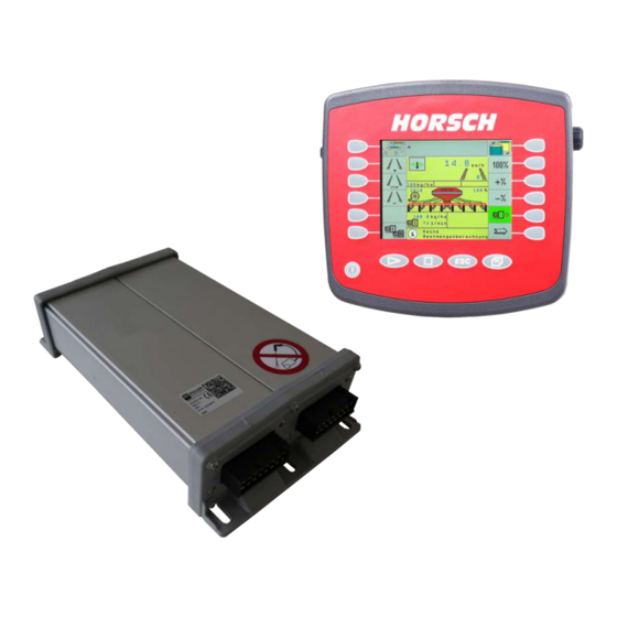
Page 6: Manager Midi
1 E-Manager Midi The E-Manager Midi is an electronic control unit for seed and fertiliser metering. The system regulates, monitors and controls all connected assembly groups of the drill. CAUTION Danger of accidents due to wrong operation. Ø Start operating the E-Manager only after reading the operating instructions. Ø... -
Page 7: Maintenance
E-Manager Midi | 1 Hardware version HORSCH material number Serial number of the job computer Job computer Job computer Master (grey lids: Midi) Plug 16-pin – connection to tractor Plug 16-pin – connection to seed flow module, slave computer or terminating resistor connector Plug 42-pin connection –... -
Page 8: Installation On Tractors Without Isobus Equipment
1 | E-Manager Midi 1.3.1 Installation on tractors without ISOBUS equipment For all tractors without ISOBUS equipment the basic equipment must be installed in the tractor during the initial installation. The cables for the basic equipment and the cable for the PowerPack must be directly connected to the tractor battery. - Page 9 E-Manager Midi | 1 1.3.1.1 Mounting the basic equipment 1. Install the terminal bracket in a suitable place within the view and the operat- ing range of the driver. 2. Install the battery cable. 3. Connect both fuse holders tightly and permanently with the cable. 4.
-
Page 10: Displays And Operating Elements
2 Displays and operating elements 2.1 Coloured softkeys Softkeys are displayed according to the equipment and configuration of the ma- chine. Various functions can be enabled or disabled with the softkeys. Some softkeys change the possible switching function with the operating condition. Enabled or selected softkeys are shaded green. -
Page 11: Colour Displays
3 Colour displays NOTE The colour bars provide a fast and helpful overview of the drilling quality. Because colour changes are noticed more quickly than numerical values reactions to changes are quicker. Green bar Green shows data and values in the tolerance range. The tolerance values are determined in the input screens by the operator and must be complied with to ensure successful placement of seed. -
Page 12: Abbreviations
4 Abbreviations Some abbreviations are used in these operating instructions and their meaning is provided in the following table. Abbreviation Meaning kg/ha Kilogram/hectare Tg/ha Thousand seed/hectare l/ha Litres/hectare Variation coefficient 1/min Revolutions per minute Millivolt – unit of electrical voltage Volt –... -
Page 13: Menu Navigation
5 Menu navigation Start Performance data 60044476 • 01 • 03/2021 • en... -
Page 14: Work Screen
6 Work screen After switching on the drill controls, the first page of the work screen will be dis- played. The displayed image will always depend on the setting and the available equipment. km/h kg/ha kg/ha kg/ha kg/ha 1/min 1/min none calc. -
Page 15: Work Screen
Work screen | 6 Post mode This softkey disables the hydraulic Lifting function. When operating the control unit only the bout marker will be selected. Reset the seed/fertiliser amount to the target value. Reduce the target value of the seed/fertiliser amount by a certain per- centage. -
Page 16: Work Screen
6 | Work screen Selection and position of the bout marker. Display of fan speed Display of metering quantity in % The percent display flashes if the placing quantity is adjusted in percent with the softkeys. In working position the coulters are displayed in black. The coulters are hidden with the tramline flaps closed and half width switched. -
Page 17: Work Screen | 6
Work screen | 6 Starting the folding process Water hole mode This function additionally appears in the symbol of the working posi- tion. On soft soils the machine can be slightly lifted. The work signal is not interrupted at this; the tram line will not count With the proportional coulter pressure system, the coulter pressure valve is selected with 0% PWM. -
Page 18: Performance Data/Results
6 | Work screen Current and rotation speed measurement Calibration Machine data Performance data/Results Display of nominal value for seed/fertiliser quantity in percent. The nominal val- ues can be changed with the softkeys -% and +%. The percentage for seed and/or fertiliser can be set on the Machine data page. -
Page 19: Current Consumption And Speeds Of Metering Motors
Work screen | 6 RESULTS quantity: area: 0.02 (sowed): 0.02 distance: 0.06 time: quantity: 0.02 area: 0.06 distance: time: 6.3.2 Current consumption and speeds of metering motors 1/min 1/min The current consumption of the metering motors is within the green range up to ap- prox. -
Page 20: Pop-Up Messages
6 | Work screen 6.4 Pop-up messages Water hole pop-up active km/h kg/ha kg/ha Water hole active kg/ha kg/ha 1/min 1/min none calc. of res. qty The pop-up is displayed as soon as the water hole mode was activated longer than one minute. -
Page 21: Calibration
7 Calibration Calibration With several metering units, switching between them can be done with the arrow keys. The menu is largely identical for all machines; several metering units may be present depending on the equipment. 1 Weigh the calibration 2 Enter the weight 3 Check the speed range Operate the calibration switch Start... -
Page 22: Entering The Nominal Value
7 | Calibration Ø Follow the quantity tables. The tables indicate the minimum and maximum placing quantities with the available rotor at different working widths and speeds (7, 9 and 12 km/h). Other rotor sizes for special applications are available on request. The settings tables are designed for a specific weight of 1 kg/litre. -
Page 23: Calibration Speed
Calibration | 7 7.1.4 Calibration speed The calibration speed can be adjusted in the respective field. A speed of 60 rpm is stored as default. This speed is sufficient under normal condi- tions. The calibration speed shall approximately correspond to the speed during field work to ensure the filling in the metering cells is roughly the same. -
Page 24: Calibrate Switch
7 | Calibration 7.1.7 Calibrate switch The calibration switch is mounted at different locations depending on the machine. Calibrate switch The following pop-up window appears if not all calibration switches are switched off: Switch off all calibration switches before start of calibration 60044476 •... -
Page 25: Start The Calibration
Calibration | 7 7.1.8 Start the calibration Ø Weigh the calibration container and write down the weight. Ø Place the container under the metering unit and open the covering. Residual quantities must be removed from the fall sluice. Ø Press the Signal light softkey to start. ð... -
Page 26: Metering Check
7 | Calibration Save calibration value? After entering the weight, the possible speed range will be calculated and displayed. If the displayed speed range conforms with your desired sowing speed, you may start sowing. If the desired working speed is not within the predefined range, the rotor must be replaced by a bigger or smaller one, as required. -
Page 27: Direct Seed Calibration Input
Calibration | 7 7.1.11 Direct seed calibration input If a product is used several times, only the initial calibration is required. Calibration factors and installed rotor need to be noted here. When using the same product again, the value for the calibration factor can be entered directly here. - Page 28 7 | Calibration 1. Make the setting for the metering motor according to the machine. From art- icle number 00111297 hydraulic metering motors 2018 are installed: Machine Setting Tiger fertiliser attachment Dosierer hydraulisch 2018 Maestro NV Dosierer hydr. 2018 NV Maestro LV Dosierer hydr.
- Page 29 Calibration | 7 The calibration process is the same for both hydraulic metering motors. 2. Close the ball valve on the fan. Ball valve on the fan closed 3. Switch on the tractor control unit for the fan. 4. Calibration, follow the Calibration section in this regard. 5.
-
Page 30: Rotors
7 | Calibration 7.1.14 Rotors NOTE Ø On machines with double fall sluice and 2 seed boxes only rotors with 2 cell discs may be used, see Notes column. Otherwise the seed is unevenly distributed to the two halves. Ø Rotors for double or quadruple fall sluices can also be used for single fall sluices. - Page 31 Calibration | 7 grain, maize, peas, beans, • not suitable for soy, spelt, sunflowers. granular fertil- iser. • Replaced in the future by Art. No. 01500600 Art. No. 01512300 grain, maize, peas, beans, • for double fall soy, spelt, sunflowers sluice • not suitable for granular fertil- iser.
- Page 32 7 | Calibration Rotors for fertiliser Rotor Size in cm³ Note Fine fertiliser for double fall sluice (2x 5) Art. No. 01508000 Fine fertiliser for double fall sluice (2x 15) Art. No. 01508100 Fertiliser Art. No. 01561900 Fertiliser for double fall sluice (2x 85) Art. No.
- Page 33 Calibration | 7 Rotors for small seeds Rotor Size in cm³ Note rape, mustard, grass seed ... Art. No. 01561200 rape, mustard, grass seed, etc. Art. No. 01504300 rape, mustard, grass seed, for double fall sluice etc. (2x 1.8) Art. No. 01509300 rape, mustard, grass seed, etc.
- Page 34 7 | Calibration Cell discs for rotor Art. No. 01504300 NOTE: The respective article number and size is engraved on the cell discs Rotor Size in cm³ Note Art. No. 01501206 Art. No. 01501201 Art. No. 01502701 Art. No. 01502703 Art. No. 01502704 60044476 • 01 • 03/2021 • en...
- Page 35 Calibration | 7 Rotors for quadruple fall sluice Rotor Size in cm³ Note rape, mustard, grass seed, etc. (4x 1.8) Art. No. 01562600 rape, mustard, grass seed, etc. (4x 5) Art. No. 01562700 grain, maize, beans, peas, soy, spelt not husked, sun- flowers Art. No.
- Page 36 7 | Calibration Rotors for MiniDrill • Use only the rotors listed here for MiniDrill. In addition, rotor 01500805 can be used (100 cm • The article numbers are engraved on the side. Rotor Size in cm³ Note rape, mustard, clover Art. No.
-
Page 37: Quantity Tables
Calibration | 7 7.1.15 Micro-granular compound calibration with separate metering units To achieve greater accuracy, the metering units of the Avatar with micro-granular compound device must be calibrated separately. The following prerequisites must be met to this end: Master Slave Hardware E-Manager Midi 3.0 E-Manager Midi Slave ex-... - Page 38 7 | Calibration Working width of the machine Volume of the recesses of the rotor for the product to be placed Intended travel speed Recommended range Increased wear on the metering unit outside these placing quantities. The actual placing quantity may differ from that displayed on the terminal. Lower/upper limit for the placing quantities Outside of these limits, an error message appears in the terminal.
- Page 39 Calibration | 7 Seed / fertiliser quantities – working width 3 m Rotor size in cm Travel speed Seed / fertiliser quantities in kg/ha in km/h lower limit recommended range upper limit min. max. 11.0 11.2 15.4 11.5 15.8 16.0 22.0 11.0 11.2...
- Page 40 7 | Calibration 30.0 40.0 80.0 110.0 15.0 20.0 40.0 55.0 10.0 13.3 26.7 36.7 36.0 48.0 96.0 132.0 18.0 24.0 48.0 66.0 12.0 16.0 32.0 44.0 1100 1024 1408 1120 1540 1200 1650 1440 1980 60044476 • 01 • 03/2021 • en...
- Page 41 Calibration | 7 1600 2200 1100 1280 2560 3520 1280 1760 1173 60044476 • 01 • 03/2021 • en...
- Page 42 7 | Calibration Seed / fertiliser quantities – working width 3.5 m Rotor size in cm Travel speed Seed / fertiliser quantities in kg/ha in km/h lower limit recommended range upper limit min. max. 13.2 13.6 13.7 18.9 19.2 26.4 13.2 19.7 27.2...
- Page 43 Calibration | 7 25.7 34.3 68.6 94.3 12.9 17.1 34.3 47.1 11.4 22.9 31.4 30.9 41.1 82.3 113.1 15.4 20.6 41.1 56.6 10.3 13.7 27.4 37.7 1207 1320 1029 1414 1234 1697 60044476 • 01 • 03/2021 • en...
- Page 44 7 | Calibration 1371 1886 1097 2194 3017 1097 1509 1006 60044476 • 01 • 03/2021 • en...
- Page 45 Calibration | 7 Seed / fertiliser quantities – working width 4 m Rotor size in cm Travel speed Seed / fertiliser quantities in kg/ha in km/h lower limit recommended range upper limit min. max. 11.6 11.9 12.0 16.5 16.8 23.1 11.6 17.3 23.8...
- Page 46 7 | Calibration 22.5 30.0 60.0 82.5 11.3 15.0 30.0 41.3 10.0 20.0 27.5 27.0 36.0 72.0 99.0 13.5 18.0 36.0 49.5 12.0 24.0 33.0 1056 1155 1238 1080 1485 60044476 • 01 • 03/2021 • en...
- Page 47 Calibration | 7 1200 1650 1920 2640 1320 60044476 • 01 • 03/2021 • en...
- Page 48 7 | Calibration Seed / fertiliser quantities – working width 6 m Rotor size in cm Travel speed Seed / fertiliser quantities in kg/ha in km/h lower limit recommended range upper limit min. max. 11.0 11.2 15.4 11.5 15.8 16.0 22.0 11.0 12.0...
- Page 49 Calibration | 7 15.0 20.0 40.0 55.0 10.0 20.0 27.5 13.3 18.3 18.0 24.0 48.0 66.0 12.0 24.0 33.0 16.0 22.0 60044476 • 01 • 03/2021 • en...
- Page 50 7 | Calibration 1100 1280 1760 60044476 • 01 • 03/2021 • en...
- Page 51 Calibration | 7 Seed / fertiliser quantities – working width 7.5m Rotor size in cm Travel speed Seed / fertiliser quantities in kg/ha in km/h lower limit recommended range upper limit min. max. 12.3 12.7 12.8 17.6 19.2 26.4 13.2 12.8 25.6 35.2...
- Page 52 7 | Calibration 12.0 16.0 32.0 44.0 16.0 22.0 10.7 14.7 14.4 19.2 38.4 52.8 19.2 26.4 12.8 17.6 60044476 • 01 • 03/2021 • en...
- Page 53 Calibration | 7 3848 1024 1408 60044476 • 01 • 03/2021 • en...
- Page 54 7 | Calibration Seed / fertiliser quantities – working width 8 m Rotor size in cm Travel speed Seed / fertiliser quantities in kg/ha in km/h lower limit recommended range upper limit min. max. 11.6 11.9 12.0 16.5 18.0 24.8 12.4 12.0 24.0...
- Page 55 Calibration | 7 11.3 15.0 30.0 41.3 15.0 20.6 10.0 13.8 13.5 18.0 36.0 49.5 18.0 24.8 12.0 16.5 60044476 • 01 • 03/2021 • en...
- Page 56 7 | Calibration 1320 60044476 • 01 • 03/2021 • en...
- Page 57 Calibration | 7 Seed / fertiliser quantities – working width 9 m Rotor size in cm Travel speed Seed / fertiliser quantities in kg/ha in km/h lower limit recommended range upper limit min. max. 10.3 10.6 10.7 14.7 16.0 22.0 11.0 10.7 21.3...
- Page 58 7 | Calibration 10.0 13.3 26.7 36.7 13.3 18.3 12.2 12.0 16.0 32.0 44.0 16.0 22.0 10.7 14.7 60044476 • 01 • 03/2021 • en...
- Page 59 Calibration | 7 1173 60044476 • 01 • 03/2021 • en...
- Page 60 7 | Calibration Seed / fertiliser quantities – working width 10 m Rotor size in cm Travel speed Seed / fertiliser quantities in kg/ha in km/h lower limit recommended range upper limit min. max. 13.2 14.4 19.8 19.2 26.4 13.2 60044476 •...
- Page 61 Calibration | 7 12.0 24.0 33.0 12.0 16.5 11.0 10.8 14.4 28.8 39.6 14.4 19.8 13.2 60044476 • 01 • 03/2021 • en...
- Page 62 7 | Calibration 1056 60044476 • 01 • 03/2021 • en...
- Page 63 Calibration | 7 Seed / fertiliser quantities – working width 12 m Rotor size in cm Travel speed Seed / fertiliser quantities in kg/ha in km/h lower limit recommended range upper limit min. max. 11.0 12.0 16.5 16.0 22.0 11.0 10.0 20.0 27.5...
- Page 64 7 | Calibration 12.0 24.0 33.0 12.0 16.5 11.0 60044476 • 01 • 03/2021 • en...
- Page 65 Calibration | 7 60044476 • 01 • 03/2021 • en...
- Page 66 7 | Calibration Seed / fertiliser quantities – working width 15 m Rotor size in cm Travel speed Seed / fertiliser quantities in kg/ha in km/h lower limit recommended range upper limit min. max. 13.2 12.8 17.6 60044476 • 01 • 03/2021 • en...
- Page 67 Calibration | 7 16.0 22.0 11.0 19.2 26.4 13.2 60044476 • 01 • 03/2021 • en...
- Page 68 7 | Calibration 60044476 • 01 • 03/2021 • en...
- Page 69 Calibration | 7 Seed / fertiliser quantities – working width 18 m Rotor size in cm Travel speed Seed / fertiliser quantities in kg/ha in km/h lower limit recommended range upper limit min. max. 11.0 10.7 14.7 60044476 • 01 • 03/2021 • en...
- Page 70 7 | Calibration 13.3 18.3 16.0 22.0 11.0 60044476 • 01 • 03/2021 • en...
- Page 71 Calibration | 7 60044476 • 01 • 03/2021 • en...
- Page 72 7 | Calibration Seed / fertiliser quantities – working width 24 m Rotor size in cm Travel speed Seed / fertiliser quantities in kg/ha in km/h lower limit recommended range upper limit min. max. 11.0 60044476 • 01 • 03/2021 • en...
- Page 73 Calibration | 7 10.0 13.8 12.0 16.5 60044476 • 01 • 03/2021 • en...
- Page 74 7 | Calibration 60044476 • 01 • 03/2021 • en...
-
Page 75: Machine Data
8 Machine data Machine data MACHINE DATA delta step delta step delta step delta step Diagnostics Automatic tram line system In the submenu, settings are made for the rhythm calculation. Calculation of residual quantity Configuration Access the work screen. Scroll to the next page. delta step Percentage by which the placing quantity is increased or reduced the pressing the corresponding softkeys. -
Page 76: Machine Data 2
8 | Machine data delta step ON / OFF Selection whether the placing quantity of the volume metering units shall be changed with the -% and +% softkeys on the work screen. 8.1 Machine data 2 MACHINE DATA Sim. speed Sim. -
Page 77: Acoustic Warnings
Machine data | 8 Enter the time delay for fertiliser metering. The delay can be between 0 and 3 seconds. Using this function, pneumatic systems of different lengths can be balanced on machines with two metering units, so that, for example, the fertiliser metering unit starts up after the seed metering unit and both media arrive at the place- ment point at the same time. -
Page 78: Tramline Control
9 Tramline control Ø Follow the operating instructions for AutoLine if AutoLine is used. During drilling, tram line tracks for spraying and spreading machines, such as crop protection sprayers, can be created. No seed or only periodical seed is then placed on these tracks. - Page 79 Tramline control | 9 In the second line a freely programmable rhythm can be entered with the R- No 999. A programmable rhythm can be selected from the table and confirmed. Ob- serve the explanation before the following tables. All rhythm numbers are specified for starting work from the left edge of a field. When starting work from the right hand headland of field the numbers must be changed accordingly.
-
Page 80: Automatic Tram Line System Selection
9 | Tramline control 9.1 Automatic tram line system selection 9.1.1 Tram line rhythm table The different tram line rhythms are shown graphically in the table. Depending on the rhythm it may be necessary to disable one half-width at the beginning. Several rhythms are possible for certain combinations of working widths of drills as well as spraying and spreading machines. - Page 81 Tramline control | 9 Length of the deactivated half-width in the first track. Length of the deactivated section in the first spraying/spreading track. Installation position of the valves when creating the tram line in one track (1/2: Half width of tram line) Installation position of the valves when creating the tram line in two tracks (1/2: Half width of...
- Page 82 9 | Tramline control • Rhythm number: 6S • The rhythm repeats after 6 tracks. • Sowing at the edge is first done with half-width shut-off. • The tram line is created in the third track. At this, track number 3 is switched off in each case at the left and right.
- Page 83 Tramline control | 9 60044476 • 01 • 03/2021 • en...
- Page 84 9 | Tramline control 60044476 • 01 • 03/2021 • en...
- Page 85 Tramline control | 9 60044476 • 01 • 03/2021 • en...
- Page 86 9 | Tramline control 60044476 • 01 • 03/2021 • en...
- Page 87 Tramline control | 9 60044476 • 01 • 03/2021 • en...
- Page 88 9 | Tramline control 60044476 • 01 • 03/2021 • en...
- Page 89 Tramline control | 9 60044476 • 01 • 03/2021 • en...
- Page 90 9 | Tramline control 60044476 • 01 • 03/2021 • en...
- Page 91 Tramline control | 9 60044476 • 01 • 03/2021 • en...
- Page 92 9 | Tramline control 60044476 • 01 • 03/2021 • en...
- Page 93 Tramline control | 9 60044476 • 01 • 03/2021 • en...
- Page 94 9 | Tramline control 60044476 • 01 • 03/2021 • en...
- Page 95 Tramline control | 9 60044476 • 01 • 03/2021 • en...
- Page 96 9 | Tramline control 60044476 • 01 • 03/2021 • en...
- Page 97 Tramline control | 9 60044476 • 01 • 03/2021 • en...
- Page 98 9 | Tramline control 60044476 • 01 • 03/2021 • en...
-
Page 99: Machine Configuration
10 Machine configuration Configuration 10.1 Configuration 1 CONFIGURATION Machine drill Additional hop hydraulic block: meter unit meter unit without differen. press. Half-wdth sh-off seedflow control: weigh system Below, the configuration options from the figures are explained. The functions are selected with yes and deselected with no. Deviating selection options will be explained in more detail. - Page 100 Seed flow monitoring Setting DickeyJ Agtron seed flow monitoring Agtron SeedControl HORSCH Observe the operating instructions for SeedControl to this end. Scroll back to the previous page. Scroll to the next page. 60044476 • 01 • 03/2021 • en...
-
Page 101: Half-Width Shut-Off
Machine configuration | 10 10.1.1 Half-width shut-off Option Machine without half-width shut-off LINAK Machine with half-width motor until 2015 LIN2016 Machine with half-width motor from 2016 The half-width motor from the year of manufacture 2016 does not have a sensor for the centre position signal and must therefore be calibrated. - Page 102 10 | Machine configuration After selecting the half-width shut-off, the second work page will show the follow- ing for switching the two half-widths on and off. kg/ha kg/ha 1/min 1/min The half-width flap is moved to the left, the right half-width of the machine is active.
- Page 103 Machine configuration | 10 kg/ha kg/ha 1/min 1/min Seed bar lifted, right half-width switched kg/ha kg/ha 1/min 1/min Seed bar lifted, left half-width switched The placing quantity is reduced by half, however, the seed quantity display remains unchanged as the working width of the machine has also been halved. The total working width is available again as soon as the softkey is pressed once more and the display shows the complete machine again.
- Page 104 10 | Machine configuration Calibrate/Teach – accept value Ø Select and confirm the position to be taught. The status point behind the field for the value is displayed as follows: • Dot transparent – position not selected • Yellow dot – position selected, motor not in teachable range •...
- Page 105 Machine configuration | 10 10.1.1.2 Checking the half-width shut-off NOTE Ø Visually check whether the correct side in the pneumatic system is shut off with the softkey for the half-width shut-off on the terminal. Ø Switch to the work screen. The half-width flap is moved to the left, the right half-width of the machine is active.
- Page 106 10 | Machine configuration NOTE Drilling error due to an incorrectly taught motor. Ø Teach the motor again if the positions do not correspond to the permissible flap positions. 10.1.1.3 Half-width shut-off with dual metering unit If under item Meter unit 1 the option dry is selected, the option 2x Dos can be selec- ted under the item Half-wdth sh-off.
-
Page 107: Liquid Fertiliser
Machine configuration | 10 10.1.2 Liquid fertiliser If the machine is equipped with the liquid fertiliser system the option liquid must be selected in the Configuration 1 screen under the item Metering unit 1. CONFIGURATION Machine drill Additional hop hydraulic block: track meter unit liquid Liquid sect. - Page 108 10 | Machine configuration rated val rated val 80.0 rated val none calc. of res. qty During drilling one can press the softkey for the metering units at the bottom left of the display. The key appears against a green background and the display shows the metering quantities for solid and liquid fertiliser.
-
Page 109: Swapping The Seed Function
Machine configuration | 10 Hopper empty. Liquid fertil placement stopped. confirm with ESC Alarm message Warning • If the alarm is confirmed with OK, the warning message on the working screen continues to be displayed. • When continuing to work with the machine, the alarm appears again after 5 seconds. -
Page 110: Metering Unit Selection
10 | Machine configuration Swap seed function from metering unit 1 to metering unit 2? The selection is discarded and the configuration is returned to. The selection is confirmed and the seed function of metering units 1 and 2 is swapped. With the swapped seed function, the target value input remains dependant on the hopper. - Page 111 Machine configuration | 10 Item Option Meaning without No additional hopper, only one seed hopper twin hopper design for fertiliser (Volume metering unit) liquid with liquid fertiliser system micro with micro granulate facility (Screw-type metering unit) 2xseed Both hoppers are used for seed. The size ratio of the hoppers is entered in the machine configuration so that both hoppers will be empty at the same time.
-
Page 112: Configuration 2
10 | Machine configuration Display additional metering units. If the machine is equipped with three metering drives or two fans the softkey can be used to toggle between the two views. NOTE If the respective metering unit type is not selected correctly, drilling errors may oc- cur because of different control parameters. - Page 113 It must be checked before use whether the terminal used allows for the function, as otherwise faults may occur when operating with SectionControl. This function is not available when using a HORSCH Basic or Comfort terminal. To this end, observe the Section Control (SC) and Variable Rate (VR) for several products section.
-
Page 114: Ut Prioritisation (Universal Terminal)
10 | Machine configuration Interruption This option is displayed when the Crossing an agricultural road is configured. Fol- low the corresponding section. Meaning Option Sowing is interrupted when lifting out. on lift out Sowing is interrupted immediately when immediately pressing the softkey. coult.press.set: If the machine is equipped with electrical coulter pressure adjustment, a setting must be made, depending on the machine type. -
Page 115: Configuration 3
Machine configuration | 10 Log off terminal? Selection Meaning The current terminal is deregistered. The working set is passed on to the next terminal and displayed there. The working signal continues to be displayed on the current ter- minal. 10.3 Configuration 3 CONFIGURATION Working width 6.00... - Page 116 10 | Machine configuration Additional key Various functions can be assigned to the key. The additional key is only available on terminals that have a different softkey ar- rangement than 2x5. Below, the configuration options from the figures are explained. The functions are selected with yes and deselected with no.
-
Page 117: Metering Unit Configuration
Machine configuration | 10 Supply The function can be used, for example, for drilling corners of the field. The speed of the volume metering unit during the flow can be entered here. time forward: When pressing the softkey Filling/pre-metering the rotor cells on the first work page or in the calibration menu, the rotor will rotate as long as specified here. - Page 118 10 | Machine configuration Calibration – metering unit 1 cal. value (calibration value) The weight in grams per rotation determined from the calibration is stored here. Follow the Calibration section in this regard. engine The drive of the metering unit is selected here. The following options are available: electrical 1: (red) electrical 2 (black) Dosierer hydraulisch...
- Page 119 Machine configuration | 10 electrical 1: (red) electrical 2 (black) Dosierer hydraulisch Dosierer hydraulisch 2018 Dosierer hydr. 2018 NV Dosierer hydr. 2018 LV cal. value 100.0 g/rev engine Dosierer hydraulisch 2018 Example – Selection: hydraulic metering motor 2018 Additional metering units, if so equipped, are displayed on the next pages. Scroll to the next page.
-
Page 120: Folding Options
10 | Machine configuration 10.3.2 Folding options If under the item Hydraulic valve block the selection Wings or Track is made, the Folding options menu appears, which allows selecting whether the Maestro is equipped with rear or lateral folding. The numbering of the subsequent pages of the Configuration menu changes then accordingly. - Page 121 Machine configuration | 10 In addition, a selection must be made whether the machine is equipped with an ad- justable axle. Next, the potentiometer for revising the position of the wings must be calibrated. Observe the section Calibrating the potentiometer to this end. Pronto 12 SW EU FOLDING OPTIONS autofolding...
- Page 122 10 | Machine configuration Each time a folding option is changed, a pop-up appears which alerts the operator to the fact that the folding configuration was changed and that collisions may occur as a result of wrong settings. After this message, manually unfold and fold in the machine completely to verify the correct folding process.
- Page 123 Machine configuration | 10 Lateral folding – example of Serto SC 10.3.2.2 Folding process Avatar SD WARNING Risk of accident through uncontrolled machine movements. Ø All fans must be turned off during the entire folding process. Ø Close the lock valve on the drawbar before each folding process. WARNING Risk of accident due to insufficient stability Ø...
- Page 124 10 | Machine configuration Lift and unfold the lateral wings. Lifting the trestle and folding in the lateral wings. Lowering the trestle. NOTE The following illustrations show a machine with full equipment. Depending on the scope of the equipment, the softkeys shown on the terminal may differ from the illustrations.
- Page 125 Machine configuration | 10 km/h kg/ha kg/ha none calc. of res. qty Starting the folding process FOLDING Unfolding For machines with sliding axle a message appears during the unfolding process that the travel speed shall be between 2 and 10 km/h. This is necessary to allow the slid- ing axle to be extended.
- Page 126 10 | Machine configuration The red X in the centre of the display indicate the status of the respective sensors (left/right). UNFOLD Ø Activate the softkey for extending the axle and operating the control unit. A message appears after the axle has been fully extended that the speed shall be less than 2 km/h.
- Page 127 Machine configuration | 10 UNFOLD The softkey for lifting and lowering the trestle becomes active from a certain posi- tion of the lateral wings. UNFOLD Ø Unfold the wings completely and then activate the softkey for lowering the trestle and operate the control unit to lower the seed bar. UNFOLD A pop-up window is displayed after the seed bar was fully lowered;...
- Page 128 10 | Machine configuration UNFOLD folding process successfully closed. Folding in Ø Pay attention to the sequence of the following steps! Ø Close the lock valve on the drawbar. km/h kg/ha kg/ha none calc. of res. qty Starting the folding process FOLDING Folding in A message is displayed at the beginning reminding to fold the railing.
- Page 129 Machine configuration | 10 FOLD IN The softkey for lifting the trestle and folding in the lateral wings is enabled. FOLD IN Ø Activate the softkey and operate the control unit to lift the trestle and fold the lateral wings. First, the distributor towers of the fertiliser equipment are fol- ded.
- Page 130 10 | Machine configuration FOLD IN The softkey for placing the wings on the hopper is enabled from a certain position of the lateral wings. FOLD IN Ø Operate the control unit and deposit the wings on the hopper. FOLD IN A message appears that the travel speed must be between 2 and 10 km/h to allow retraction of the axle.
- Page 131 Machine configuration | 10 FOLD IN The softkey for retracting the axle is enabled as soon as the travel speed lies in this range. FOLD IN Ø Activate the softkey and operate the control unit to retract the axle. FOLD IN A popup window is displayed as soon as the axle is fully retracted;...
- Page 132 10 | Machine configuration FOLD IN folding process successfully closed. Check transport width! WARNING Danger of traffic accidents due to exceeded transport width. Ø Check the maximum permissible transport width before travelling. Ø Confirm the pop-up window with OK. This completes the folding in process of the machine. 10.3.2.3 Folding process Serto SC WARNING Risk of accident through uncontrolled machine movements.
- Page 133 Machine configuration | 10 The display shows the symbols with a grey shade. Only activated symbols appear in their full colour. Once the conditions for the next work step are fulfilled, the display of symbols will change from shaded to full colour and the next step can be executed. Folding menu If the folding process is aborted, this warning will be displayed for a few seconds: FOLD IN...
- Page 134 10 | Machine configuration FOLDING Folding menu Unfolding 5. Select the Unfolding hydraulic function in the display. The machine must be folded in at standstill or at a speed of less than 2 km/h. The folding menu will only be enabled at a speed of less than 2 km/h. If the speed is exceeded when switching on the folding menu, this notice will appear: UNFOLD 6.
- Page 135 Machine configuration | 10 UNFOLD 7. Press the softkey for folding the distributor towers, the track loosener and the attachment trestle as well as the control unit. It becomes shaded green. UNFOLD UNFOLD The softkey can be activated to lower the trestle once the distributor towers are fully unfolded.
- Page 136 10 | Machine configuration UNFOLD The following message is displayed after the unfolding process has been fully com- pleted: UNFOLD folding process successfully closed. 9. Confirm the message. 10. Open the lock valve on the drawbar. Folding in CAUTION Damage to the machine caused by collision. Ø...
- Page 137 Machine configuration | 10 km/h kg/ha kg/ha none calc. of res. qty Work screen – Folding process softkey active Starting the folding process FOLDING Folding menu Folding in Select the folding in hydraulic function in the display. The machine must be folded in at standstill or at a speed of less than 2 km/h. The folding menu will only be enabled at a speed of less than 2 km/h.
- Page 138 10 | Machine configuration FOLD IN 5. The following warning reminds you of the railing on the access steps. The railing must be folded in to transport position before folding; damage to wings or the railing may otherwise occur. This must be confirmed in the E- Manager before folding in.
- Page 139 Machine configuration | 10 7. Activate the softkey and operate the control unit until the distributor towers are folded in and the track looseners are retracted and the trestle is in the cor- rect position. This is indicated on the display by the green checkmarks. FOLD IN Distributor towers folded in The softkey for folding in the seed bar will be enabled after the distributor towers...
- Page 140 10 | Machine configuration FOLD IN The following message is displayed after the folding in process has been fully com- pleted: FOLD IN folding process successfully closed. Check transport width! 10. Check the transport width and confirm the message. WARNING Danger of traffic accidents due to exceeded transport height.
- Page 141 Machine configuration | 10 WARNING Dropping or lowering machine parts may cause severe crushing in- juries etc.! Ø No persons may stay under raised machine parts! Ø Order persons to leave the danger zone around the machine. Make sure be- fore folding that no persons are present in the danger zone.
- Page 142 10 | Machine configuration km/h kg/ha kg/ha none calc. of res. qty Starting the folding process FOLDING Unfolding 5. Actuate the softkey for unfolding the wings: Unfolding the wings UNFOLD 60044476 • 01 • 03/2021 • en...
- Page 143 Machine configuration | 10 6. Unfold the wings until the softkey for lowering the trestle has been activated: Lowering the trestle. UNFOLD 7. Press the softkey to lower the trestle: UNFOLD 8. Lower the trestle until the softkey hook is activated: UNFOLD 60044476 •...
- Page 144 10 | Machine configuration 9. Confirm the message of the successful completion of the folding process by pressing OK: UNFOLD folding process successfully closed. Folding in CAUTION Danger of damage to the machine. Ø Secure the power harrow in the transport position to prevent the rotor from moving during road transport.
- Page 145 Machine configuration | 10 FOLDING Unfolding The following message indicates that the access ladder must be folded up before starting to drive. 4. Fold up the ladder and confirm the message with OK: FOLD IN 5. Press the softkey to lift the trestle: Lift the trestle.
- Page 146 10 | Machine configuration 6. Check whether the ladder is folded in. 7. Continue lifting the trestle: FOLD IN As soon as the distributor towers are correctly folded in this is indicated by green checkmarks in the display: FOLD IN 8.
- Page 147 Machine configuration | 10 FOLD IN 10. Confirm the message of the successful completion of the folding process by pressing OK: FOLD IN folding process successfully closed. Check transport width! WARNING Danger of traffic accidents due to exceeded transport height. Ø...
- Page 148 10 | Machine configuration 13. Insert both bolts for the anti-fold mechanism. To this end, loosen the cotter pin on the bolt, insert the bolt for the anti-fold mechanism and secure it again with the cotter pin. Anti-fold mechanism bolt 10.3.2.5 Short-circuit/wire break on the wing potentiometer Working position pot.
-
Page 149: Configuration 4/5 - Device Geometry
Machine configuration | 10 CALIBRATION 0°: 90°: potentiometer use poti? : Calibration – potentiometer configured use poti? : points to yes. In the event of a problem with the potentiometer this value can be set to no; a working signal is then permanently present. The potentiometer is then no longer analysed. -
Page 150: Asymmetric Equipment Geometry
10 | Machine configuration If more than three products are configured, another screen is shown on which the dimensions for the metering units of the missing products can be entered: Scroll to the next page. machine geometry 0.00 10.4.1 Asymmetric equipment geometry machine geometry 0.00 0.00... - Page 151 Machine configuration | 10 Example Seed wagon symmetry axis Seed bar symmetry axis No offset Seed wagon symmetry axis Seed bar symmetry axis Offset Offset between seed wagon and seed bar 60044476 • 01 • 03/2021 • en...
-
Page 152: Configuration 5/6
Calibrate/Teach – accept value Calibration of the wing potentiometer. View additional fans. This function is only provided for HORSCH Service. km/h – Source of the speed signal for the drill Selection of speed signal. The following options are available: tractor radar – Option for utilising the speed signal from the radar sensor of the tractor if available. - Page 153 Machine configuration | 10 pulses tractor radar tractor wheel J1939 GPS Working position Selection of source for the working signal. switch Factory setting; with this option the work signal is defined via the working switch on the machine. TECU This option can be selected if the machine is connected to the three-point or tractor link arm.
-
Page 154: Extra Key Selection
NOTE The Extra key selection is only available for terminals with an arrangement of 2 x 5 softkeys, such as the HORSCH key terminal. 10.6.1 Setting 1. Select the Yes option on the Configuration menu under the item Extra key se- lection. - Page 155 Machine configuration | 10 Selection of function to be replaced A list with all available functions appears: List of available functions 2. Select and confirm the desired function. The selected softkey replaces the previous operating element. km/h Tg/ha kg/ha kg/ha Nom.
-
Page 156: Functions Of The Selectable Softkeys
10 | Machine configuration 10.6.2 Functions of the selectable softkeys Tram line Plus This softkey can be used to advance within the rhythm, if necessary, for example, if row counting was interrupted with the softkey Tram line STOP. Tram line Minus This softkey can be used to jump back within the rhythm, if necessary, for example, if the machine was lifted out by accident. - Page 157 Machine configuration | 10 Water hole mode This function additionally appears in the symbol of the working posi- tion. On soft soils the machine can be slightly lifted. The work signal is not interrupted at this; the tram line will not count With the proportional coulter pressure system, the coulter pressure valve is selected with 0% PWM.
- Page 158 10 | Machine configuration WorkLight Pro settings The half-width flap is moved to the left, the right half-width of the machine is active. The half-width flap is moved to the right, the left half-width of the machine is active. Focus drilling depth adjustment Drill function main switch Reducing the coulter pressure Increasing the coulter pressure...
-
Page 159: Additional Key Selection
Machine configuration | 10 10.7 Additional key selection Additional key Various functions can be assigned to the key. The additional key is only available on terminals that have a different softkey ar- rangement than 2x5. km/h kg/ha none calc. of res. qty Work screen with additional key CONFIGURATION Working width... -
Page 160: Crossing An Agricultural Road Function
10 | Machine configuration 10.7.1 Crossing an agricultural road function Agricultural road crossing This function can only be selected via the Extra key selection or the Ad- ditional key. The selection is made as described in the section Extra key selection. This function is intended for temporarily switching off drilling without having to shut down the machine, e.g. - Page 161 Machine configuration | 10 10.7.1.1 Control when lifting out When selecting when lifting out the softkey can be pressed before reaching the rural road or water hole. The machine can then be lifted out at the rural road or water hole. Drilling is inter- rupted.
-
Page 162: System Restart Pop-Up
10 | Machine configuration 10.7.2 System restart pop-up The system must be restarted after changing the configuration options. Correspond- ing pop-up windows are displayed. If a pop-up with the OK button is displayed, this button must be pressed to restart the system. -
Page 163: Calculation Of Residual Quantity
11 Calculation of residual quantity This function calculates the distance and area that can still be cultivated with the seed remaining in the hopper. The current hopper content must be entered before work begin to allow performing the calculation correctly. The residual quantity calculation can be activated or deactivated for each hopper. -
Page 164: Optional Equipment
Work screen – Workingset Partner Partner can be selected as additional machine type. If a Partner FT is combined with a HORSCH rear implement, 2 working sets are dis- played on the terminal. For this purpose, both machines must be connected on the same ISOBUS and one master computer each must be installed. -
Page 165: Partner As Slave: No
Configuration Partner solo Perform settings analogous to a HORSCH drill. Partner + additional HORSCH implement One device is configured as slave, the other as master (main working set). Partner + additional HORSCH implement Both devices must be operated with the on the same ISOBUS software 10.06 or higher. -
Page 166: Partner As Slave: Yes
12 | Optional equipment CONFIGURATION extra key select show header : JD Split-Screen TC Multi product TC funct. disabled Drill depth adj. AutoLine Half-wdth sh-off coult.press.set: Hydac Power harrow 12.1.2 Partner as Slave: yes NOTE To enable connecting a partner as slave with the master computer, both machines must be operated with the same master software. - Page 167 Optional equipment | 12 Partner as Slave Setting Configuration Partner in connection with another HORSCH implement on the ISOBUS. Partner in solo operation Operating hours counter of the Partner Software version on the job computer of the Partner Status regarding the connection to the second implement.
- Page 168 12 | Optional equipment Option Explanation Operation in combination with Partner on the ISOBUS. Operation of an individual machine on the ISOBUS. Configuration options auxiliary hopper The softkey is shown as soon as an auxiliary hopper is configured. CONFIGURATION Maschinentyp Partner single hop meter unit Half-wdth sh-off...
- Page 169 Optional equipment | 12 Working position The options yes and no are available. It must be defined whether the working position signal is sent by the Partner. Option Meaning The working position signal is sent by the Partner to the job computer.
-
Page 170: Partner Twin Hopper
(B) can be entered. The hopper ra- tio of 60 : 40 is stored as default. 12.2 Partner With this software the Solo operation of the HORSCH Partner as well as the combin- ation with another HORSCH implement is possible. 12.2.1 Partner solo... -
Page 171: Partner With Maestro Rc - 1 Job Computer
Optional equipment | 12 Terminal ISOBUS Battery ISOBUS socket Front hopper Job computer Working signal sensor ISOBUS socket Maestro RC connection or seed flow monitoring 12.2.2 Partner with Maestro RC – 1 job computer Maestro RC Front hopper ISOBUS connection Terminal Working signal sensor Battery... -
Page 172: Partner With Maestro Rc - 2 Job Computers
12 | Optional equipment 12.2.3 Partner with Maestro RC – 2 job computers Maestro RC Front hopper Job computer ISOBUS connection Terminal Working signal sensor Battery ISOBUS connection Job computer 12.3 LED working lights 12.3.1 WorkLight These operating functions appear automatically in the machine data area when LED working lights (WorkLight) are connected and a fault-free CAN-Bus connection is available. -
Page 173: Worklight Pro
Optional equipment | 12 MACHINE DATA Sim. speed km/h Sim. speed delta step delta step Machine data 2 - WorkLight Pro not connected 12.3.2 WorkLight Pro For various machine, working lights with individual LED headlights are available as an option. km/h Tg/ha kg/ha... - Page 174 12 | Optional equipment WorkLight Pro settings Work light WorkLight Pro settings The LED headlights can be arranged and switched in up to four sections. The light grey sections indicate a blind cap which means that no headlights are available. Switching the selected section on/off.
-
Page 175: Material Flow Monitoring
Setting DickeyJ Agtron seed flow monitoring Agtron SeedControl HORSCH Observe the operating instructions for SeedControl to this end. Setup of material flow monitoring The job computer is restarted after selecting DickeyJ. The following message is dis- played once after the restart: Seed flow system inactive! No DJ sensors allocated. -
Page 176: Dickey-John Configuration
12 | Optional equipment NOTE The message indicates that the system is not active until the exact Dickey-John con- figuration has been performed. Dickey-John configuration must be performed again when the machine type is changed. 12.4.2 Dickey-John configuration Before the Dickey-John configuration can be carried out, the configuration of the drill must be completed. - Page 177 Optional equipment | 12 Loop 1 Loop 2 Loop 3 Loop 4 - - - - Option Explanation Selection when a metering unit is not equipped with material flow monitoring. All rows of the product half-width are set to Loop = 1 and Sensor = 0.
- Page 178 31-row machines. All rows of this product half-width are not changed when pressing the HORSCH softkey again. The number of installed sensors must be determined after assigning the loops. The configured number of rows is suggested as number of sensors. Normally, assign- ment takes place automatically but must be verified.
- Page 179 Optional equipment | 12 NOTE Changes to the assignment need to be made only when the number of rows and sensors does not agree, for example, when a sensor fails. In case of two loops per metering unit, the sum of the sensors of both loops must always be entered under number of sensors.
- Page 180 12 | Optional equipment Automatic sensor config. All settings for which “----” is not selected will be reset. The sensor configuration is overwritten automatically after confirming the pop-up. The sensors must be reassigned. No action is performed if the message is cancelled. In the Dickey-John configuration only one sensor can be assigned to each row.
- Page 181 Optional equipment | 12 sensitivity seed Fertiliser Sensitivity setting in 9 stages Stage Explanation Very few small grains are sufficient to detect material flow. Very many large grains must drop through the sensor to detect ma- terial flow. Sensitivity must be set before starting to sow. Increase the sensitivity with the + but- ton until warning messages from sensors are displayed on the terminal during nor- mal operation (no seed hose blocked).
- Page 182 12 | Optional equipment 12.4.2.2 Individual sensor assignment If a machine is to be operated with an individual sensor, coulter and loop assign- ment, the following setting must be made for all loops: - - - - - - - - - - - - - - - - Material flow monitoring detail assignment (assignment of the coulter)
- Page 183 Optional equipment | 12 Assignment of the seed/fertiliser flow sensor. With this assignment it is also not necessary to exactly assign the sensor to the respective coulter. It is sufficient when the section and the loop are assigned matching each other. “0”...
-
Page 184: Summarizing Sensors
12 | Optional equipment Loop 1 missing sens. 1 - 2 : Loop 2 missing sens. 1 - 2 : Material flow monitoring test function The sensor values are reset and the function can be tested. The material flow can be simulated manually. The status must be checked. - Page 185 Optional equipment | 12 CONFIGURATION The previously used setting, in which the number of coulters remains unchanged even though half of the coulters are not installed, can still be used. The number of sensors per row must not be increased. The working mode remains the same, how- ever, the correct row spacing is not recorded since the machine continues to as- sumed a narrower row spacing with 40 coulters.
-
Page 186: Section Control And Variable Rate For Several Products
12 | Optional equipment 12.5 Section Control and Variable Rate for several products In order to be able to use the functions Section Control (SC) and Variable Rate (VR), the following prerequisites must be fulfilled: • ME Touch 1200 with software version 02.03.13 or higher or another terminal that supports this function. - Page 187 Optional equipment | 12 TC settings TC-SC TC-GEO Selection Section Control/Variable Rate TC-SC correction The delay times for Section Control during activation or deactivation can be set on this page. TC-SC correction km/h 10.0 10.0 0.00 2.50 0.00 1.50 0.00 2.50 0.00 1.50...
-
Page 188: Horsch Singularsystem With Funck Metering Unit
Additional hop hydraulic block: meter unit meter unit without differen. press. Half-wdth sh-off seedflow control: singulation Ø Unter dem Punkt singulation auswählen, ob die Maschine mit dem HORSCH SingularSystem mit Funck_Dosierer betrieben wird. 60044476 • 01 • 03/2021 • en... -
Page 189: Prerequisites
• The seed must have a uniform size. The seed must be examined with the en- closed shaker box. • The recommendations by HORSCH regarding the dressing to be used must be followed. • Foreign objects in the seed and other contamination must be reduced to a min- imum. - Page 190 12 | Optional equipment CALIBRATION turns correct? rotor cells filled? 2. calibration ca. turns 1/min Rotor speed during the calibration process 3. Use only the scales supplied (15 kg scale division: 1 g) for the calibration. Precision scales 4. The scales must be placed on level ground. 5.
-
Page 191: Settings
Optional equipment | 12 Calibration box 6. Note the deviation of the weighing results from the specification on the ter- minal. It may be 20 g at the most. CALIBRATION turns correct? rotor cells filled? 3. set seedrate cal. value 2.104 ca. -
Page 192: Overview Page
12 | Optional equipment Status of variation coefficient (VC) Colour Meaning green VC very good yellow VC satisfactory VC poor or sensor soiled 12.6.5 Overview page The overview page shows all metering units and associated sensors. none calc. of res. qty Indicate the motor utilisation. - Page 193 Optional equipment | 12 Metering unit status Colour Meaning Symbol green The metering unit is run- ning with the specified parameters. yellow The metering unit controls, the speed is adjusted. The metering unit is blocked. 12.6.5.1 Calibrating the motors Calibration of the motors is required under the following circumstances: •...
- Page 194 12 | Optional equipment 12.6.5.2 Indicating motor utilisation Indicate the motor utilisation. The utilisation of the metering motors can be read on a bar diagram. When idling, motor utilisation should be approximately 10% for all metering units. 1. In case of deviations, check the distance of the metering discs of the respective metering units.
- Page 195 Optional equipment | 12 12.6.5.3 Metering units detail view Metering units detail view Metering units detail view Select the respective row per rotary wheel or touch to navigate to the detail view. Disabled metering motors are not displayed. Motors that were disabled because of overload appear red. The page with the detail view of the row appears after selecting a particular row.
- Page 196 12 | Optional equipment control The status point is coloured analogues to the point on the overview page. green Metering motor at working speed. yellow Metering motor in control. Metering motor blocked sensor Indicates the degree of contamination of the sensor. green Sensor in order.
- Page 197 Optional equipment | 12 1. Verify before installing the pockets whether the speed range indicated corres- ponds to the planned working speed. The table shows reference values for the number of pockets in the speed range between 8 - 12 km/h. To select the pockets, check the permissible speed range in the E-Manager.
- Page 198 12 | Optional equipment crop type Select the type of fruit. Enter the Thousand Seed Weight. distance Display of the theoretical grain spacing. gr./rev Select number of pockets. min. speed Display of minimum possible working speed. max. km/h Display of maximum possible working speed. offset nm.
-
Page 199: Configuration
Optional equipment | 12 12.6.6 Configuration 12.6.6.1 Rows and sensors CONFIGURATION Machine drill Additional hop hydraulic block: meter unit meter unit without differen. press. Half-wdth sh-off seedflow control: singulation Two downpipe sensors are factory-mounted on each machine and allocated to the respective row. - Page 200 12 | Optional equipment NOTE After changing the number of modules, the modules must be addressed again in the diagnostics menu. Press the corresponding softkey in the diagnostics menu. Addressing modules Alternatively, the seed bar together with the modules can remain installed. In this case, each module has only one motor connected.
-
Page 201: Commissioning And Change Of Fruit Type
Optional equipment | 12 12.6.7 Commissioning and change of fruit type Several steps are required with commissioning and when changing fruit types in or- der to utilise the singulation system: 1. Check the suitability of the seed with the shaker box. Note the section Suitabil- ity of seed in this regard. -
Page 202: Calibration Travel
12 | Optional equipment 12.6.8 calibration travel A calibration run can be carried out to optimise the singulation result and to reduce possible faults in operation. The speeds of the individual Funck metering units are individually adjusted during calibration travel. Refer also to the Fruit parameter section in this regard. Calibration travel can be carried out for grain. - Page 203 Optional equipment | 12 Cancel the process with X. A message is displayed if the machine with the seed used was not yet calibrated: No data available from calibration mode for this seed type. A message then appears stating that a calibration must be carried out before the start of the calibration travel: Machine must be calibrated before start none...
- Page 204 12 | Optional equipment 3. Depending on the application (calibration travel in the hall or in the field), ac- tivate the corresponding metering units. If required, the metering units can be switched off individually. Select the symbol of the metering unit, depending on the terminal, with a rotary wheel or touch and click.
- Page 205 Optional equipment | 12 Working speed Enter the working speed. The desired working speed that shall later be run in the field is entered here. The nominal speed must be between 1000 and 1800 rpm. To achieve uniform placement, the speed entered must be maintained dur- ing calibration travel.
- Page 206 12 | Optional equipment Number of pockets min. speed km/h max. km/h 14.0 km/h The message can be confirmed with the checkmark button. If the displayed speed range does not agree with the actual speed range or the number of pockets is faulty, the screen for changing the settings can be accessed with the wrench button.
- Page 207 Optional equipment | 12 The following message is displayed after the successful check: Test: OK none calc. of res. qty The following screen is displayed if faults occur on one or several Funck metering units: Test: not OK please check row: none calc.
- Page 208 12 | Optional equipment Calibration process starts automatically as soon as machine is lowered; please move forward to prevent seed accumulation; Recommended speed: 10.0 km/h Remain time: Sec. none calc. of res. qty The calibration process starts when the machine is lowered. If the machine is lifted out before the end of the calibration travel, the calibration process is interrupted and continued when the machine is lowered again.
-
Page 209: Reactivating The Funck Metering Units
Optional equipment | 12 If the nominal speed is adjusted globally for all Funck metering units on the Fruit parameters mask, the following message appears: Results of calibration mode are reset If the machine is lifted out during calibration travel, the following message appears: Calibration process interrupted. - Page 210 12 | Optional equipment km/h gr/m² gr/m² 1/min 1. Select the drill in the display with the rotary wheel or by touching. The row overview page is displayed. 24.3 Metering units detail view 2. Press the softkey. The overview page on which the blocked rows are shown in red is displayed: Overview page –...
-
Page 211: Singularsystem Troubleshooting
Optional equipment | 12 Metrunit curr. Rev 1/min nm. rot. spd. 1/min act. current 0.000 control Nom. freqncy Gr/s Reactivating the metering unit It indicates that the motor is no longer turning. The motor concerned can be restar- ted without calibration using the Reactivate metering unit softkey. This softkey is only shown when the motor supplies on of the ErrorCodes listed at the beginning. - Page 212 Dressing too sticky. Check whether the dress- ing used for the singulation system is approved by HORSCH. Dismantle the Funck metering unit, if necessary, and continue drilling without singulation. Fan speed too low Select a higher fan speed.
- Page 213 Optional equipment | 12 The variation coefficient is The downpipe sensors are Remove the metering unit poor (red status). soiled. and clean the downpipe with the supplied brush. Observe the downpipe sec- tion in the operating in- structions on the Singu- larSystem.
-
Page 214: Focus Drilling Depth Adjustment
12 | Optional equipment 12.7 Focus drilling depth adjustment An optional electro-hydraulic drilling depth adjustment is available for the Focus TD. To operate the adjustment function, a slave extension job computer is required. Two valves and special cylinders allow setting a default placing depth and a greater placement depth. - Page 215 Optional equipment | 12 The limit target value for the first product determines when the drilling depth is switched over. The drilling depth range set in the lower range is active from a target value of 0 kg/ha up to and including the limit target value. In case of target values above the limit target value, switching over to the drilling depth range set above is done.
-
Page 216: Diagnostics
13 Diagnostics Diagnostics 13.1 Diagnostics program RES. QUANTITIES Master slave 1 slave 2 fold. computer DJ seed flow WorkLight Pro total count./SW NOTE Different points are displayed according to the equipment and configuration of the machine. Ø Select and confirm the desired diagnostics area. 13.1.1 Main computer (Master) 13.1.1.1 Diagnostics 1 DIAGNOSE... - Page 217 Diagnostics | 13 pulses The pulses are counted after switching the metering unit on. Curr consumpt (mA) Display of current consumption of metering motor in mA. Metering unit Monitoring of the filling level in the metering unit to monitor seed bridging. When the metering unit is empty nothing will be placed.
- Page 218 13 | Diagnostics NOTE The leak must be corrected at any rate. Calibrate switch Status Terminal display Calibration switch switched off Calibration switch switched on Working position Here the work signal of the hydraulic pressure switch can be checked. Status Terminal display Machine lowered Machine lifted...
- Page 219 Diagnostics | 13 13.1.1.2 Diagnostics 2 DIAGNOSE Master Metering motor2 pulses Curr consumpt (mA) Metering unit Fan pulses fill.level differen. press. Calibrate switch Working position Radar pulses half-wdth. Linak The half-width flap is moved to the left, the right half-width of the machine is active.
- Page 220 13 | Diagnostics differen. press. On machines with pressurized hopper, the leak tightness of each hopper is mon- itored by a sensor. In case of a leaking hopper the rotor may not be filled correctly with seed or fertil- iser. This reduces the amount of seed or fertiliser actually placed. If the machine is in working position, the differential pressure can only be analysed when the fan is switched on.
- Page 221 Diagnostics | 13 CAUTION Danger of drilling faults due to incorrectly switched half-width flaps. Ø Always check through visual inspection whether the half-width flap was switched correctly. 13.1.1.3 Diagnostics 3 DIAGNOSE Tram line left Tram line right Coulter pressure Tram line right ON The valves for the right tram line must close.
- Page 222 13 | Diagnostics 13.1.1.4 Diagnostics 4 On this screen the proper function of the half-width shut-off can be checked. The menus differ depending on the half-width motor installed. DIAGNOSE half width left half width Mitte half width right The half-width flap is moved to the left, the right half-width of the machine is active.
- Page 223 Diagnostics | 13 Simultaneous disabling of all activated functions. WARNING Risk of injury by unwanted hydraulic movements. If the valve control takes place via the diagnostic area, the user is responsible. Ø Operate the machine with extra caution. Ø Stop hydraulic movements in case of faults. Lift/lower the machine Lifting and lowering the machine.
-
Page 224: Slave Computer 2
13 | Diagnostics collisions possible Warning note for Slave valve diagnostics WARNING Risk of injury by unwanted hydraulic movements. If the valve control takes place via the diagnostic area, the user is responsible. Ø Operate the machine with extra caution. Ø... - Page 225 Diagnostics | 13 Switching metering unit 3 on and off pulses The pulses are counted after switching the metering unit on. Curr consumpt (mA) Display of current consumption of metering motor in mA. Fan pulses When the fan is running the pulses are continuously counted. fill.level If the filling level is fallen short of, the info line will show a warning.
-
Page 226: Folding Computer
13 | Diagnostics 13.1.3 Folding computer DIAGNOSE inclin. sensor left ° inclin. sensor rt ° mean value ° curr. left right Here, the inclination sensors of a Pronto 12 SW EU can be checked. In the upper section the values of the inclination sensors are displayed and the re- spective current consumption at the bottom edge of the display. - Page 227 Diagnostics | 13 Diagnostics 2 DIAGNOSE sensor axle: sensor axle: sensor tower: The function of the hydraulic valves as well as the switching functions of axle and tower sensors can be checked in this menu. In case of a wing control failure, the switching functions of the machine can be used to fold the machine to transport or working position.
- Page 228 13 | Diagnostics 13.1.4.1 Warning note for valve diagnostics When choosing the diagnostics screen for the valve control on all machines with lat- eral folding, a message appears which points to possible dangers that may arise in case of manual valve control. This must be confirmed with the displayed OK button. collisions possible Warning note for Master valve diagnostics collisions possible...
- Page 229 Diagnostics | 13 13.1.4.2 Manual wing control WARNING Risk of accident through uncontrolled machine movements. Ø All fans must be turned off during the entire folding process. Ø Close the lock valve on the drawbar before each folding process. WARNING Risk of injury and machine damage through unintentional hydraulic movements.
- Page 230 13 | Diagnostics Folding in the Avatar SD DIAGNOSE sensor axle: sensor axle: sensor tower: Ø Switch off all fans and fold in the railing by hand. Pay attention to the operat- ing instructions of the machine at this. Ø Remove the aluminium clips from the support wheels. Folding the distributor towers in and out.
- Page 231 Diagnostics | 13 Unfolding the Avatar SD DIAGNOSE sensor axle: sensor axle: sensor tower: Extending or retracting the axle The position of the axle is indicated in the display under the items Sensor axle retracted or Sensor axle extended for left and for right each with 0 or 1.
- Page 232 13 | Diagnostics Folding in the Serto SC DIAGNOSE sensor tower: Ø Switch off all fans and fold in the railing by hand. Pay attention to the operat- ing instructions of the machine at this. Ø Remove the aluminium clips from the support wheels. Block up / down The position of the trestle is presented by the display value of the po- tentiometer.
- Page 233 Diagnostics | 13 Unfolding or folding in wings toward front Attention! The towers must be folded in transport position. The trestle must be lifted approx. 75° (Maestro CX/CV: 65°). Ø Select the softkey and operate the control unit to completely fold in both wings.
- Page 234 13 | Diagnostics Folding the distributor towers in and out. Ø Select the softkey and actuate the control unit to unfold the distributor towers completely. The display must show a 0 for both indications of the tower posi- tions. Block up / down The position of the trestle is presented by the display value of the po- tentiometer.
- Page 235 Diagnostics | 13 Ø Select the softkey and operate the control unit to completely fold in both wings. Retract and extend the packer. Ø Select the softkey and actuate the control unit to retract the packer to trans- port width. Ø...
-
Page 236: Material Flow Monitoring
13 | Diagnostics Folding the catwalk and the distributor towers in or out. Ø Select the softkey and actuate the control unit to unfold the distributor towers and the catwalk. Block up / down The position of the trestle is presented by the display value of the po- tentiometer. -
Page 237: Worklight Pro
Diagnostics | 13 Loop 2 voltage A voltage B Indicates the values for the output voltages in Loop 1. The voltage values must lie between 11.5 V and 14 V. As soon as a second material flow module is installed, switching to the second dia- gnostics page is possible with the arrow softkey. -
Page 238: Total Count./Sw
13 | Diagnostics 13.1.7 total count./SW Counter quantity: 1179 T gr area: distance: 10.6 time: hours: The total output of the machine is shown in the middle of the screen. quantity: The quantity counters count the placed amount of products. area: The total area is increased when the machine is working. - Page 239 Diagnostics | 13 Master Indicates the software version of the master computer. Object-Pool The Object Pool shows the version of the screen pool. slave 1 slave 2 Here the software versions of the installed slave computers are displayed. Job computer Name on job computer Slave 1 Slave...
-
Page 240: Diagnostics Pronto 12 Sw Eu
13 | Diagnostics 13.1.7.1 Error memory ErrorCodes In the error memory all ErrorCodes with their number (A) and the exact time stamp, consisting of date (B) and time (C), are listed. If no time stamp was filed, no time stamp of the terminal was available on the bus when the error occurred. - Page 241 Diagnostics | 13 Unfolding in the diagnostic menu Representation Implement position Function 270 – 180° 90° folding 180° Raising the coulter at the far end 180 – 90° 180° folding 90° Lowering the coulter at the far end 90 – 0° 180°...
-
Page 242: Jd Split Screen
14 JD Split Screen When selecting the option yes in the Configuration 2 menu under the item JD Split- Screen, two softkeys appear. They are only visible when using certain terminals. The softkeys can be arranged on the user interface with the terminals. CONFIGURATION extra key select show header :... - Page 243 Notes 60044476 • 01 • 03/2021 • en...
- Page 244 60044476 • 01 • 03/2021 • en...
- Page 246 All details on technical specifications and illustrations are approximate and non-binding. Subject to technical product revisions.
Need help?
Do you have a question about the E-Manager Midi 10.13 and is the answer not in the manual?
Questions and answers