Table of Contents
Advertisement
Quick Links
Advertisement
Table of Contents

Subscribe to Our Youtube Channel
Related Manuals for Iso-Tech LCR 1705


Summary of Contents for Iso-Tech LCR 1705
- Page 1 Instruction Manual LCR 1705 / 1707 Smart tweezers LCR Tester LCR 1707 ...
- Page 2 Safety sheet Warning Warning Safety sheet ........
-
Page 3: Maintenance
Symbols as marked on the Meter and Instruction manual Risk of electric shock See instruction manual AC measurement DC measurement Battery Fuse Earth Equipment protected by double or reinforced insulation Conforms to EU directives Do not discard this product or throw away. -
Page 4: Meter Description
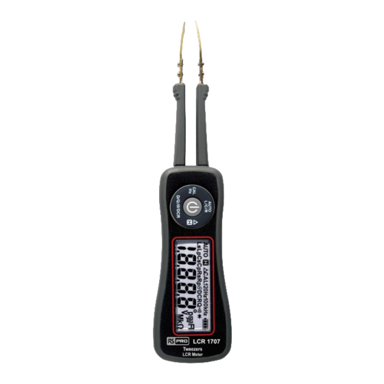
Meter Description 1. Test probes 2. Push buttons for features 3. LCD display: 20,000 counts 4. Mini USB plug for charge & connect to PC Assembly 1. USB cable 2. AC adaptor (for 1707) 3. L Type Test probes & special screws x 4 (for 1707) 4. - Page 5 Measuring Principle ...
- Page 6 Phase Drawing The phasor is a constant complex number, usually expressed in exponential form, representing the complex amplitude (magnitude and phase) of a sinusoidal function of time. When θ (phase) > 0° Then Z (impedance) is Capacitive reactance When θ (phase) < 0° Then Z (impedance) is Inductive reactance When θ...
-
Page 7: Making Basic Measurements
Making Basic Measurements Preparation and Caution Before Measurement Observe the rules of WARNING and CAUTION Discharge the DUT (Device Under Test) before connecting the test probes. The figures on the following pages show how to make basic measurements. Power On/Off Press the central power button to turn on. - Page 8 Measuring L/C/R The auto test mode is the default mode when the meter is turned on. When the meter in auto test mode, it will automati- cally detect the DUT and show the suitable result on the dis- play. ˙In auto test mode, press the AUTO L/C/R button to enter manual test mode.
- Page 9 Select Test Frequency The default test frequency is 1kHz when the meter is turned on. Press the Cal/Hz button to select the test frequency. Open/Short Calibration In order to achieve the best measuring result, the calibration has to be done before measuring the DUT. To calibrate the meter, press and hold the Cal/Hz button >...
- Page 10 "Srt" blinks about 15 sec When “Srt” appears on the display, make the test probes short closely, and press the Cal/Hz button to start short calibration. During short calibration, the “Srt” blinks on the display. About 15 seconds later, the result of the short calibration appears on the display.
- Page 11 Hold Press the Δ/H button to enter the hold mode. The meter holds the last reading and shows the indication “H” on the display. Press the Δ/H button again to exit the hold mode. Relative Δ Press and hold the Δ/H button > 2 sec to start the relative mode. The meter stores the last reading as reference and shows the indication “Δ”...
- Page 12 Charge There is a Li-ion battery as power source in the meter. When the battery indicator shows low battery, charge the meter as soon as possible. When battery charge complete, the battery indicator will show full level on the display. ˙Always use the typical mini USB plug adaptor to charge.
-
Page 13: General Specifications
General Specifications Display : 20,000 counts Polarity Indication : Automatic, positive implied, negative indicated. Over Range Indication : OL Measuring Rate : 2.5 samples per second Internal Power Requirements : 3.7V / 400mAh Li-ion Battery External Power Requirements : USB plug or AC Adapter Battery Life : 20 hours typical (no backlight) Battery Charge Cycle : 2 hours typical Low Battery Voltage : 3.8V... -
Page 14: Electrical Specifications
Electrical Specifications ˙Accuracy is ± (% of reading + LSD) ˙Ambient temperature: 23°C ± 5°C (< 80% RH) Test Frequency Model Frequency Accuracy 100Hz 120Hz 1705/1707 1kHz ± 0.2% 10kHz 1707 100kHz Test Signal AC Signal Level: 600mVrms AC Signal Accuracy: ± 20% DC Bias Level: 800mV DC Bias Accuracy: ±... - Page 15 Inductance 100Hz Range 1kHz 10kHz 100kHz 120Hz 20.000uH 0.5% + 30 200.00uH 0.5% + 30 0.5% + 5 2000.0uH 0.5% + 30 0.5% + 5 0.5% + 5 20.000mH 0.5% + 30 0.5% + 5 0.5% + 5 1.0% + 5 200.00mH 0.5% + 5 0.5% + 5...
- Page 16 Resistance 100Hz Range 1kHz 10kHz 100kHz 120Hz 20.000Ω 0.5% + 50 0.5% + 50 0.5% + 50 200.00Ω 0.5% + 8 0.5% + 8 0.5% + 8 0.5% + 8 2.0000kΩ 0.5% + 5 0.5% + 5 0.5% + 5 0.5% + 5 20.000kΩ...
-
Page 17: Limited Warranty
Limited Warranty This meter is warranted to the original purchaser against defects in material and workmanship for 3 years from the date of purchase. During this warranty period, RS Components will, at its option, replace or repair the defective unit, subject to verification of the defect or malfunction. - Page 18 Asia Iso-Tech 460 Alexandra Road, #15-01A PSA Building Singapore 119963 7410 Pebble Drive Fort Worth Texas 76118-6961 Europe Iso-Tech PO Box 99 Corby Northamptonshire NN17 9RS United Kingdom Canada 1701 Woodward Drive Ste 108 Ottawa Ontario K2C 0R4, Canada Japan...
Need help?
Do you have a question about the LCR 1705 and is the answer not in the manual?
Questions and answers