Table of Contents
Advertisement
Quick Links
©The Craftsman Gallery • PO Box 54518 • Cincinnati, OH 45254 • email: info@thecraftsmangallery.com
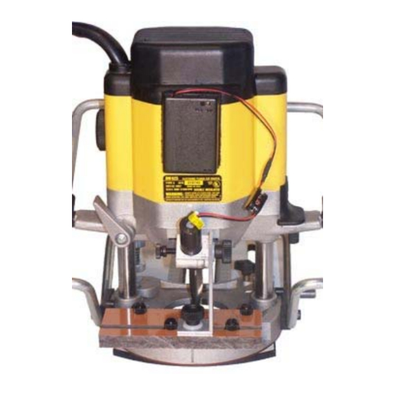
Instructions for mounting Laser Guide to DeWalt 625 plunge router
Attach mounting plate
Attach laser guide mounting plate to rear
base of router using two 6mm x 20mm
nylon screws.
Attach laser bracket
Assemble laser bracket as shown. The lower
knob screws into a t-slot nut which slides
into mounting plate t-slot. Ridge in bottom
of bracket fits into t-slot to keep the bracket
square with mounting plate.
Insert stops
Assemble two stops using a ¼" nylon screw
and t-slot nut for each. On each side of
laser bracket, slide a stop into mounting
plate t-slot.
Mount laser unit
Insert laser unit into holder on laser bracket
and tighten thumb screw to secure the unit.
Tip of laser unit should protrude only slightly
below the holder.
Advertisement
Table of Contents

Related Manuals for Craftsman DeWalt 625


Summary of Contents for Craftsman DeWalt 625
- Page 1 ©The Craftsman Gallery • PO Box 54518 • Cincinnati, OH 45254 • email: info@thecraftsmangallery.com Instructions for mounting Laser Guide to DeWalt 625 plunge router Attach mounting plate Attach laser guide mounting plate to rear base of router using two 6mm x 20mm nylon screws.
- Page 2 Attach battery pack Remove backing paper from Velcro strips and stick Velcro to back of router and to back of battery pack as shown. Press the Velcro together to attach battery pack to router. The Velcro allows the battery pack to be easily removed and reattached.
- Page 3 ©The Craftsman Gallery • PO Box 54518 • Cincinnati, OH 45254 • email: info@thecraftsmangallery.com Technique for cutting Dowel Joints and Dados with WoodRat ® using our laser guide, brass gauge bars, quick clamp, plunge bar and router bits Plunge cut an alignment hole Select and chuck a straight bit.
- Page 4 Mark positions of dowels Layout dowel positions on boards to be jointed. Clamp board to machine With layout marks on top, clamp board to be jointed onto sliding bar flush with underside of base plate. Position for dowel hole Loosen star knob to free router movement. Power feed board and position router so that center of cross hair is positioned on location for dowel.
- Page 5 Plunge bit Turn on router and plunge bit to depth stop to cut dowel hole. Repeat for remaining dowels Repeat above procedure to drill any additional dowel holes in the board. Mark position of dado cut We will use a dovetail bit to cut a stopped dado for a sliding dovetail.
- Page 6 Position for dado Loosen star knob to free router movement. Position board and router so cross hair line of laser overlays line marking dado location. Tighten star knob. Set plunge depth Zero bit on top of board. Use brass gauge bar to set router depth stop to desired depth for the dado cut.
Need help?
Do you have a question about the DeWalt 625 and is the answer not in the manual?
Questions and answers