
Summary of Contents for Hawk AT300-V2
- Page 1 AT300-V2 / AT300PS-V2 AMPHIBIOUS EXCAVATOR OPERATION, INSTALLATION, AND MAINTENANCE MANUAL CERT NO: TUV100 01 2043 ISO 9001: 2015 HawkExcavator.com...
- Page 2 The Amphibious Hydraulic Excavator AT300-V2/AT300PS-V2 with two pontoons is a type of fully multi-purpose hydraulic excavator developed and manufactured by HAWK Excavators. It is designed for use on soft ground, marshland, as well as in shallow water. This manual will help users understand the structure, features, and functions of this machine in a thorough and systematic way, to facilitate operation and maintenance.
-
Page 3: Table Of Contents
TABLE OF CONTENTS DESCRIPTION PAGE MAIN SPECIFICATIONS MAIN PERFORMANCE PARAMETERS OPERATING CONDITIONS 1.2.1 ALLOWABLE CONDITIONS 1.2.2 NON-ALLOWED CONDITIONS STRUCTURE PARKING BRAKE OPERATION PRECAUTIONS BEFORE USING A NEW MACHINE 3.1.1 INSPECT THE FOLLOWING ITEMS BEFORE OPERATING OPERATING THE MACHINE 3.2.1 PRECAUTIONS 3.2.2 TRAVELING ON LAND 3.2.3... - Page 4 MAINTENANCE GENERAL SAFETY PRECAUTIONS INSPECTION, MAINTENANCE INTERVALS AND ITEMS PERIODIC MAINTENANCE REQUIREMENTS FOR PERFORMING INSPECTION AND MAINTENANCE 15 INSPECTION AND MAINTENANCE (BEFORE OPERATING MACHINE) OTHER MAINTENANCE 5.4.1 TRAVEL DEVICE 5.4.2 TIGHTENING OF THE SLEWING FRAME MOUNTING BOLT 5.4.3 ADJUSTING TRACK TENSION AND GREASING TRACK CHAINS 5.4.4 WEAR PLATES INSTALLATION AND TRANSPORTATION TRANSPORTATION...
-
Page 5: Main Specifications
1.0 MAIN SPECIFICATIONS 1.1 MAIN PERFORMANCE PARAMETERS ITEM UNIT SPECIFICATION REMARKS AT300-V2/AT300PS- MAIN MODEL HIGH QUALITY QUANTITY: 4 TRAVEL MOTOR HYDRAULIC MOTOR MOTOR/SET ORIGIN: KOREA HIGH QUALITY SPUD POLE QUANTITY: 2 HYDRAULIC MOTOR MOTOR MOTOR/SET ORIGIN: KOREA GROUND km/h 0-3.2 (0-1.9) -
Page 6: Operating Conditions
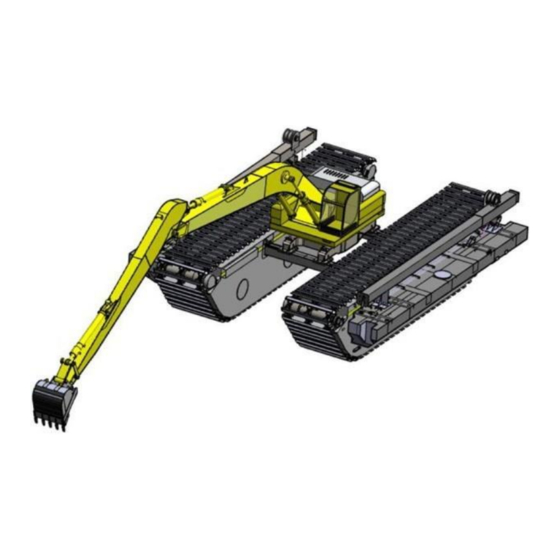
The machine is only used for light loads and shouldn't be used for heavy loads. 2.0 STRUCTURE The AT300-V2/AT300PS-V2 hydraulic amphibious excavator has four traveling devices (two traveling motors per amphibious undercarriage). Figure 2.0 shows a simple drawing of the structure of the machine. -
Page 7: Parking Brake
Figure 2.0: Amphibious Undercarriage Structure 2.1 PARKING BRAKE The machine normally comes with a closed-type brake, which is an automatic brake device using spring force when the excavator is parked on a slope. When the machine is working, the brake valve on the travel motor will automatically be released each time the travel foot pedal is activated to move forward or backward. -
Page 8: Operating The Machine
OPERATING THE MACHINE 3.2.1 PRECAUTIONS Thoroughly check the pontoons for cracks and leaks before traveling on marshland or water. If any defects are found, stop using the machine immediately. Proceed with the inspection, and repair the defects accordingly. The chain must be correctly tensioned during operation, because if the machine takes a turn on marshland and its chain is too loose, misalignment may occur. -
Page 9: Entering The Water
When traveling on water, the requirements for water speed, wave height, and wind speed are as follows: a) The water speed should be less than 24 m/min (1.31 feet/second). b) The wave height should be less than 0.1 m (3.93 in). c) The wind speed should be less than 240 m/min (8.94 mph). -
Page 10: Avoid Excavation Work While Floating
Figure 3.2: Launching the Amphibious Excavator Avoid parking the amphibious excavator in the water. Refer to Figure 3.3. Figure 3.3: Avoid parking in the water 3.2.6 AVOID EXCAVATION WORK WHILE FLOATING The amphibious excavator is designed to work on soft ground. Therefore, avoid letting it float in water while working. -
Page 11: Landing
3.2.7 LANDING Methods similar to those applied when entering the water also apply when exiting the water and returning to land. Choose a suitable hard slope and position to exit. Be sure to move to an upright position when landing. The boom and arm should be in the forward position as shown in Figure 3.5. -
Page 12: Spud Working Procedure
3.2.9 SPUDS WORKING PROCEDURE (HORIZONTAL TO VERTICAL POSITION) Open the 3/4” three-way valves ‘A’ and ‘B’, located at the rear of the slewing frame to activate the spud system. Refer to Figure 3.6. Valves ‘A’ and ‘B’ Figure 3.6: Spud ball valve position on the rear slewing frame Two pieces of 1/2”... - Page 13 Three way ball valve ‘C’and ‘D’ Figure 3.7: Position of the three-way ball valves to control the spud Two-way ball valves are used to control the flow of hydraulic fluid: To the spud cylinder for extending or retracting actions. To the motor to raise the spud up and down. These valves must be manually adjusted by the amphibious excavator operator.
-
Page 14: Spud Position During Traveling
Lock the Spud Figure 3.9: Spud locking pin 3.2.10 SPUD POSITION DURING TRAVELING (HORIZONTAL POSITION) Pull out the spud’s locking pin. Slowly control the travel lever to raise the spud until it reaches the limit plate. Refer to Figure 3.10. Start traveling. -
Page 15: General Safety Precautions
4.1 GENERAL SAFETY PRECAUTIONS Inspection and maintenance can be performed by parking the machine on a solid, level surface. Make sure the inspection and maintenance are carried out in good weather conditions. The inspection and maintenance of hydraulic components should be carried out where there is less dust. -
Page 16: Inspection And Maintenance (Before Operating Machine)
Figure 5.0: Amphibious excavator position for maintenance Before performing any inspection or maintenance on the machine, place an “INSPECTION / MAINTENANCE IN PROGRESS" sign in a place visible to others, to avoid unwanted incidents. Refer to Figure 5.1. Figure 5.1: Sign during inspection and maintenance INSPECTION AND MAINTENANCE (BEFORE OPERATING MACHINE) Suggested period for inspection and maintenance activity: Inspection and maintenance activities... -
Page 17: Other Maintenance
Loosened or falling out bolts, nuts, and gaskets. a) Daily Tension track chain and check for abrasion or Monthly damage to the track shoes. Do if necessary Lubricate the chain Long time parking: weekly Working: monthly Monthly Tightening the locking screw of the slewing frame Do if necessary Condition of the amphibious undercarriage body and its parts... -
Page 18: Tightening Of The Slewing Frame Mounting Bolt
Oil level check Inlet point Horizontal Oil Outlet Level Figure 5.3: Checking the oil level To check the oil level, park the machine on level ground. Rotate the travel motors until the oil level checkpoint is approximately horizontal to an imaginary line as per figure 5.3. IMPORTANT: The oil level checkpoint must be higher than the horizontal oil level before removing the plug. -
Page 19: Adjusting Track Tension And Greasing Track Chains
5.4.3 ADJUSTING THE TRACK TENSION AND GREASING THE TRACK CHAINS To tension the track, first loosen the hex nut-A and then loosen the hex nut-B as shown in Figure 5.5. Unscrew the adjusting bolts (M36) to increase the tension of the track chains. Make sure that the tensions of both amphibious undercarriages are the same. -
Page 20: Installation And Transportation
6.0 INSTALLATION AND TRANSPORTATION 6.1 TRANSPORTATION For transportation purposes, all parts of the AT300-V2/AT300PS-V2 must be disassembled before being loaded onto the truck trailer. Follow the instructions in section “6.4 DISASSEMBLING THE MACHINE” to do the disassembly process. Load the amphibious parts carefully and make sure they are well placed and secure. - Page 21 Figure 6.2 Install the crossbeams on the inner C-Chamber of one of the undercarriage bodies, according to the correct position. Use the locking pin to lock the crossbeams. Refer to Figure 6.3. Lock Pin Figure 6.3 Move the second undercarriage unit to the preassembled unit. Insert the undercarriage into the crossbeam.
- Page 22 Figure 6.4 Place the slewing frame on the crossbeams. Align the slewing frame mounting flange with the crossbeam mounting flange. Refer to Figure 6.5. Figure 6.5 Tighten the slewing frame upper mounting flange onto the bottom mounting flange as shown in Figure 6.6. There are a total of 32 bolts at the four corners that need to be tightened.
- Page 23 24 NOS – M30 x 110L hex bolt c/w flat washer, spring washer and nylon lock nut 8 NOS – M30 x 60L hex bolt c/w spring washer and nylon lock nut Figure 6.6 Install the excavator’s upper body and attachments by referring to the manual and guidelines provided by the upper body manufacturer.
- Page 24 Figure 6.7 Install the hydraulic hoses from the pontoon to the slewing frame and from the slewing frame to the upper body center joint. Then install the hydraulic hoses one at a time by removing the protective caps, and attaching the hoses to the right fitting. Check all connections for proper tightness.
-
Page 25: Assembling The Side Pontoons
ASSEMBLING THE SIDE PONTOONS Using the crane, lift the side pontoon and make sure that the center of the side pontoon box beam is aligned with the S-chamber of the pontoon. Insert the side pontoon box beam into the S-chamber of the pontoon. Lock the side pontoon by inserting the locking pin as shown in Figure 6.10. -
Page 26: Disassembling The Machine
Figure 6.11 Hydraulic connection Figure 6.12 6.4 DISASSEMBLING THE MACHINE The disassembling sequences of the amphibious hydraulic undercarriage are as follows: Disconnect all hydraulic hoses from the center joint and slewing frame. Caution on hydraulic oil spills. Plug open hoses with caps or plugs. Remove the hydraulic cylinder pins from the undercarriage hydraulic cylinder brackets (it is not necessary to remove the hydraulic cylinder from the slewing frame). - Page 27 Thank you for taking the time to read this manual. We hope you have a pleasant experience using our Amphibious Excavator AT300-V2/AT300PS-V2. For any further information, do not hesitate to contact us. HawkExcavator.com/contact Version-2 11/16/2021 HawkExcavator.com...
Need help?
Do you have a question about the AT300-V2 and is the answer not in the manual?
Questions and answers