
Summary of Contents for Riken Keiki OX-500
- Page 1 PT2E-1161 OPERATING INSTRUCTION MANUAL RIKEN INDOOR OXYGEN MONITOR MODEL OX-500...
- Page 2 Introduction Thank you for your order of Riken Oxygen Monoxide (OX) monitor, Model OX-500. The instrument is to notify the concentration of oxygen deficiency by alarm lamp or buzzer to prevent oxygen deficiency accident by any chance. To operate the instrument correctly, make sure to understand the manual before operating.
- Page 3 Danger ・ The OX-500 should not be wired parallel to the wires which include power source, high hertz , high voltage and any other instruments’ wires. ・The intersect wiring should be done when the OX-500 is to intersect with high hertz, high voltage and wires.
-
Page 4: Table Of Contents
Table of Contents Page 1. Name of Each Part and Function …………………………………… 5 2. Place to Install ……………………………………………………… 3. How to Install ……………………………………………………… 3-1 How to Install …………………………………………………… 3-1-1 When Using Attached Mounting Panel……………………… 3-1-2 When Not Using Attached Mounting Panel ……………… 3-2 Take in Power Supply Directly ………………………………... - Page 5 6. Connect Wiring ………………………………………………………… 7. External Output Operation …………………………………………… 7-1 External Output ………………………………………………… 7-2 4-20mA Output Chart …………………………………… 7-3 LED, Contact Point Output Chart …………………………… 8. When Instrument is Not in a Good Condition ……………………… 9. Specifications ……………………………………………………… 10. Accessories ………………………………………………………...
-
Page 6: Name Of Each Part And Function
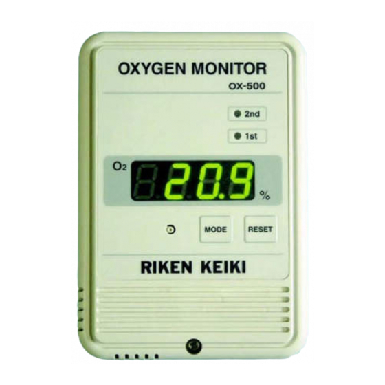
1. Name of Each Part and Function 【 Front Side】 Power Switch Alarm Lamp(Red) Flashes when OX concentration becomes below AL.2. Display Displays concentration and message. Alarm Lamp(Orange) Flashes when OX concentration becomes below AL.1. “RESET” Switch “MAINTE” Switch “MODE” Switch Hole to pull out cable Select one of the four places depend on installation place. -
Page 7: Place To Install
2. Place to Install Install the instrument on the wall where 50~80cm away from the floor.(Make sure not to install the instrument where blasting directly from conditioning.) 50~180cm Please do not install the instrument in the following places. 1.Get direct sunlight or at outside 2.Easy to get wet 4. - Page 8 Cautions for Usage 1. Open the window and ventilate 2. Plug in the power plug into the the air in the room. outlet and turn on the power source. display starts flashing seconds later after all lamps are on. 3. The air adjustment should be done. Since it is not guaranteed whether the instrument reading is appropriate against the oxygen concentration when recovery from the power failure or after power switch is ON, make sure to execute the air adjustment.
-
Page 9: How To Install
3. How to Install 3-1 How to Install Caution Installation should be done before AC power source is connected. Otherwise, you will get an electrical schok. 3-1-1 When Using Attached Mounting Panel ①Fix attached panel to wall surface with attached screws (pan head screw or screw spike). - Page 10 ③Confirm whether the back of the lower part of the case is attached closely to the attached panel. ◎Good example ×Bad example Caution When you install, be careful not to pinch the cable between the body of the instrument and the attached panel. ④The air adjustment will be done when the instrument becomes measurement mode after plugging in the AC code into the outlet and turn on the power source.
-
Page 11: When Not Using Attached Mounting Panel
3-1-2 When Not Using Attached Mounting Panel ①Loosen the screw of the lower part of the front body of the instrument and open the upper case Loosen the screw ②Open the upper part case and take off the connector which is connected to the bottom case. - Page 12 ③Fix on two places of the bottom case with attached two screws (pan head small screw or screw spike.) At this time, confirm whether the instrument is not inclined. Fix to wall 83.5mm(matched to surface by screw switch box) Caution ・Fix the panel to the wall, which is strong enough and doesn’t vibrate.
-
Page 13: Take In Power Supply Directly
3-2 Take in Power Source Directly Caution Installation should be done before AC power source is connected. Otherwise, you will get an electrical shock. 3-2-1 How to Connect AC Cable ①Loosen screws of lower part of the front body of the instrument, and open the upper case. - Page 14 ④Fix the power source cable with the cable clamp. 60± mm from leading 3 0 edge Cut from the base 【Back of the case】 Surface AC cable *Note ・ The position to fasten the cable clamp is 60± 3 mm from 0...
- Page 15 ⑤Let the cable clamp through the hole to pull out the cable, and fix the power cable. Cable clamp Hole to pull out cable AC cable (Let the cable clamp through beneath of the hole to pull out cable) *Note ・...
-
Page 16: Cable Using
⑦Close the case ⑧Turn the power ON Caution ・ Cables, except for AC cable, should be basically wired into the wall via switch box. In case the cable will be wired outside of the wall, fix the cable where the unnatural power will be placed since there is no cable through cramp. -
Page 17: How To Use
4. How to Use 4-1 Operational Flow after Power Source is On 4-1-1 Self Diagnosis Confirm the setting status of the indicator after the power source is on. Green 4-20mA output:17.4mA fixation 4-1-2 Initial Clear Initial clear is the warm up time before sensor output becomes stable. The time for the initial clear is 25 seconds including the self diagnosis time. -
Page 18: Basic Function
The alarm start flashing and buzzer will beep when the gas concentration rate is less than the alarm setting rate. The Model OX-500 has 2 decrease alarms function (L/LL). Orange or Red ※ The standard of alarm operation is the automatic return after self maintenance reset. -
Page 19: Indication When Trouble Occurs
4-2-4 Indication When Trouble Occurs There are two kinds of troubles, i.e. memory error and breaking of wire error. The error notice will be displayed and buzzer will beep when error occurs. ①Memory error Turn off the power is the only way to release the memory error. Memory error:... -
Page 20: User's Maintenance Mode
Once you press the “MODE” button continuously for 3 seconds when the “Measuring Mode” is indicated, the LEDs turns to the “User Maintenance Mode”. The Model OX-500 has five user’s maintenance mode: “Air Adjustment”, “Alarm Point Confirmation”, ”Alarm Summary Confirmation”, “Date & Time Confirmation・Set-up”, and “Alarm Test”. -
Page 21: Air Adjustment
5-1 Air Adjustment It is the mode to control the present gas concentration to “20.9”. ① Green “MAINTE” for 3 seconds RESET ② Green (flashing) Air Adjustment Complete Air Adjustment Inability ② Green (Measuring Mode) RESET ③ Red ① ≪Air Adjustment Menu≫ Press the ”MODE”... -
Page 22: Alarm Point Confirmation
5-2 Alarm Point Confirmation It is a mode to confirm the alarm point. ① Green RESET RESET ② Orange MODE ③ RESET ① ≪Alarm Point Menu≫ Press the ”MODE” button, the LEDs display the “Alarm Summary Menu”. Press the “RESET” button, the LEDs display the “Alarm Confirmation 1”. ②... -
Page 23: Alarm Summary Confirmation
5-3 Alarm Summary Confirmation It is the mode to confirm the alarm summary. The indications are “Track Record No.” (AL.P1、AL.P2…) “Gas Concentration”, “Year”, “Month & Date”, “Time”. It can confirm 10 cases maximum. ① Green RESET ② Green RESET №1 MODE ③... - Page 24 ② ≪Track Record Indication≫ Track record 1(P1)will be displayed. Press the “MODE” button, it goes to the “Indication for Concentration”. Press the ”RESET” button, it goes to the “Alarm Summary Confirmation Menu”. ③ ≪Indication for Concentration≫ The Alarm Summary Concentration will be displayed. Once the recorded concentration is in the 1 alarm time, the indication of the concentration will become orange.(1st LED flashing)...
-
Page 25: Date & Time Confirmation・Set-Up
5-4 Date & Time Confirmation・Set-up This is the mode to confirm and set up the date & time of the inner clock. Green RESET “MAINTE” 【Date & Time Setting Mode】 【Date & Time Confirmation Mode】 ① ≪Date & Time Confirmation・Set-up Menu≫ Press the ”MODE”... - Page 26 【Date & Time Confirmation Mode】 ① ≪Date & Time Confirmation・Set-up ① Green Menu≫ When you press the ”RESET” button, it will return to the “Date & Time RESET Confirmation Year”. ② Green ② ≪Date & Time Confirmation Year≫ Current year will be displayed. RESET MODE Press the “MODE”...
- Page 27 【Date & Time Set-up Mode】 ① Green “MAINTE” ② Green “MAINTE” ③ Green “MAINTE” ④ Green “MAINTE” ⑤ Green “MAINTE” ⑥ Green “MAINTE” ① ≪Date & Time Confirmation・Set-up Menu≫ Press the “MAINTE” button, it goes to the “Date & Time Set-up Year”. ②...
- Page 28 ③ ≪Date & Time Set-up Month≫ Current date will be displayed. (Indication for the Month will be flashed.) Press the “RESET” button and the Month which is indicated will go UP. (If you keep pressing it, the Month will go UP continuously) Press the “MODE”...
-
Page 29: Alarm Test
5-5 Alarm Test ① ≪Alarm Test Menu≫ Press the “MODE” button, it will return to the “Measuring Mode”. ①Green Press the “MAINTE” button, it goes to the “Alarm Test 0 “ mode. RESET “MAINTE” ② ≪Alarm Test 0≫ ②Green Test rate Air (20.9) will be displayed. Press the “MODE”... -
Page 30: Connect Wiring
6. Connecting Wire ① + AC100V50/60Hz 【Standard】 DC24V±10% 【Option】 ② - ③ Grounding Terminal ① 4-20mA Output shield wire(2 cores) ② - ③ ⑥ ⑤ AL1 Alarm Point Output ① ⑥ ② AL2 Alarm Point Output ⑦ ③ ⑧ ④ ・... -
Page 31: 4-20Ma Output Chart
7-2 4-20mA Output Chart Status Output mA Remarks Initial 17.4 Fixed rate Normally (No alarms) 4.0~20.0 Depending on gas concentration Scale Over 20.1~22.0 Depending on gas concentration Trouble Fixed rate User Maintenance Mode Menu 4.0~22.0 Depending on gas concentration Maintenance Mode Menu 17.4 Fixed rate Air Adjustment... -
Page 32: When Instrument Is Not In A Good Condition
8. When Instrument is Not in a Good Condition (1)Power source is not ON. ・ Power source is not pluged in → Connect the power source code to the plug ・ Power source switch is OFF → Turn on the power switch ・... -
Page 33: Specifications
9. Specifications Model OX-500 Detected Gas Oxygen (O2) Sampling Method Diffusion sampling Detection Principle Galvanic cell Sensor Model OS-B11 Detected Range 0~25.0 vol % (0.1 vol %) (1 digit) Display 3 digits 3 colors LED(Green, Orange, Red) Normal:Green Gas alarm: 2 decrease alarms, latching mode (Non-latching with... -
Page 34: Accessories
10. Accessories Connecting Panel (1 piece) ※It is connected to the body of the instrument. Pan head small screw (2 pieces) Small spike(2 pieces)... -
Page 35: Warranty
RIKEN KEIKI STANDARD WARRANTY GAS DETECTION INSTRUMENTS RIKEN KEIKI CO., LTD. warrants gas alarm equipment manufactured and sold by us to be free from defects in materials and workmanship for a period of one year from date of shipment from RIKEN KEIKI CO., LTD. Any parts found defective within that period will be repaired or replaced, at our option, free of charge, F.O.B.
Need help?
Do you have a question about the OX-500 and is the answer not in the manual?
Questions and answers