
Summary of Contents for Brightlink BLIP-A300TR-P-P
- Page 1 User Manual BLIP-A300TR-P-P 4K IP Streaming Transceiver (with Preview) All Rights Reserved Version: IPA300/ BLIP-A300TR-P- P_2020V1.0...
- Page 2 BRIGHTLINK 4K IP AV DISTRIBUTION Preface Read this user manual carefully before using the product. Pictures shown in this manual are for reference only. Different models and specifications are subject to real product. This manual is only for operation instruction, please contact the local distributor for maintenance assistance.
- Page 3 BRIGHTLINK 4K IP AV DISTRIBUTION SAFETY PRECAUTIONS To ensure the best performance from the product, please read all instructions carefully before using the device. Save this manual for further reference. Unpack the equipment carefully and save the original box and packing material for ...
-
Page 4: Table Of Contents
1.3 Package List ...................... 2 2. Specification ....................... 3 3. Panel Description ......................4 3.1 IPA300/ BLIP-A300TR-P-P Front Panel ..............4 3.2 IPA300/ BLIP-A300TR-P-P Rear Panel ..............4. System Connection ..................... 6 4.1 Usage Precaution ....................6 4.2 Connection Type ....................6 4.3 System Diagram .................... - Page 5 BRIGHTLINK 4K IP AV DISTRIBUTION 5.7 HDMI Audio Routing Tab ................. 22 5.8 Analog Audio Routing Tab ................24 5.9 RS-232 Routing Tab ..................25 5.9.1 Assign Transmitter to all Receivers ............26 5.9.2 Sending RS-232 Data from IPA Manager to a Device ......26 5.10 Infrared Routing Tab ..................
-
Page 6: Product Introduction
BRIGHTLINK 4K IP AV DISTRIBUTION 1. Product Introduction The BLIP-A300TR-P-P is a network AV Transceiver with HDMI input and output up to resolution 4K@60Hz 4:4:4, HDR. It is designed for HDMI transmission over IP network with external audio and control signals at distance up to 100m over CATx cable. -
Page 7: Features
receiver embedding. BlueRiver™ Series is compatible with SDVoE, offering zero-latency AV-over-IP with true 4K@60 and video processing. Note: BLIP-A300TR-P-P supports video preview on the IPA manager software, while BLIP-A300TR-P can’t. 1.3 Package List 1x BLIP-A300TR-P-P 2x Mounting Ears with 2 ... -
Page 8: Specification
BRIGHTLINK 4K IP AV DISTRIBUTION 2. Specification Input Video Input (1) HDMI Video Input Connector (1) Type-A female HDMI HDMI Input Resolution Up to 4Kx2K@60Hz 4:4:4 8bit Output Video Output (1) HDMI Video Output Connector (1) Type-A female HDMI HDMI Output Resolution... -
Page 9: Panel Description
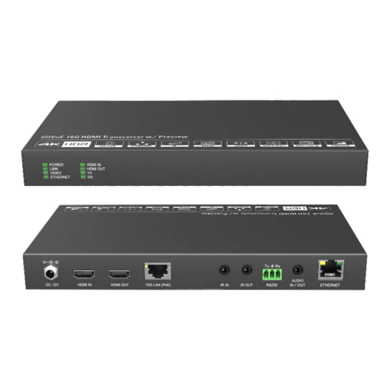
BRIGHTLINK 4K IP AV DISTRIBUTION 3. Panel Description 3.1 IPA300/ BLIP-A300TR-P-P Front Panel ① POWER LED: The LED illuminates green when power is applied. LINK LED: The LED indicates green if 10G LAN port is connected. VIDEO LED: The LED illuminates green when the stable video signal is detected. -
Page 10: 3.2 Ipa300/ Blip-A300Tr-P-P Rear Panel
BRIGHTLINK 4K IP AV DISTRIBUTION 3.2 IPA300/ BLIP-A300TR-P-P Rear Panel ① DC 12V: DC port for AC power adapter connection. ② HDMI IN: Type-A female HDMI port to connect HDMI video source device. ③ HDMI OUT: Type-A female HDMI port to connect HDMI display device. -
Page 11: System Connection
4K@60Hz 4:4:4 resolution as well as 1G Ethernet, audio and control signals over a single copper cable. Splitter (One-to-Many) With only one BLIP-A300TR-P-P as transmitter and one 10G Ethernet witch, any A/V signal can be flawlessly and instantly distributed to a near limitless number of receivers and screens, any number of times. -
Page 12: System Diagram
BRIGHTLINK 4K IP AV DISTRIBUTION 4.3 System Diagram The following diagram illustrates typical input and output connections that can be utilized with the BLIP-A300TR-P-P: Matrix System... -
Page 13: Hardware Setup
10) Connect a 10G Ethernet cable (Cat-6a recommended) from the 10GbE port each TX and RX unit to any available 10GBaseT port. 11) Connect the control PC to the GbE port of any BLIP-A300TR-P-P device or to a Cat-x port of the 10GbE switch (except the management/console port of the switch). - Page 14 BRIGHTLINK 4K IP AV DISTRIBUTION use a 10GbE layer 2, layer 3 switch with IGMP snooping capabilities. Ensure that the IGMP snooping setting is enabled and broadcast setting is disabled using the appropriate configuration software provided by the switch manufacturer.
-
Page 15: Operation Of Ipa Manager
5.1 General Information The IPA Manager is a demonstration control software used to configure and control signal extension, routing and switching between BLIP-A300TR-P-P units. The IPA Manager includes Web GUI version and Windows PC version. The control PC can be connected to the ETHERNET port of any device or to any RJ45 port of the 10GbE switch except the management/console port of the switch which is not part of the network. -
Page 16: Device Configuration
BRIGHTLINK 4K IP AV DISTRIBUTION 5.2 Device Configuration Before starting the IPA Manager application, make sure it is connected either directly to the network switch or to the Gigabit Ethernet port on one of the devices. Now launch the application. Upon launch, the IPA Manager main window will open up in the “Video Switching”... -
Page 17: Start Ipa Manager
BRIGHTLINK 4K IP AV DISTRIBUTION 5.3 Start IPA Manager Start the evaluation by launching the Manager Client. The application will start and appear as illustrated below. First, connect to the Control Server by entering the IP address of the device running the NT Control Server and click CONNECT. -
Page 18: Video Routing Tab
BRIGHTLINK 4K IP AV DISTRIBUTION 5.4 Video Routing Tab The "Video Routing" tab is used to manage signal routing between TX and RX devices. There are different video modes available: Genlock Mode This mode simulates a cable connection. When Genlock is selected, the output is a byte-by-byte replication of what was received from the source. -
Page 19: Video Switching
BRIGHTLINK 4K IP AV DISTRIBUTION 5.4.1 Video Switching This is an example of joining TX and RX devices in "Genlock Mode": 1) Verify that the RX tile is displaying that the device is currently in "Genlock Mode". If Genlock is not the currently active mode, apply the setting as described: a) Right mouse click the gear icon on the respective Receiver (RX) tile. -
Page 20: Stopping/Starting Video
BRIGHTLINK 4K IP AV DISTRIBUTION 5.4.3 Stopping/Starting Video To stop video being transmitted from a Transmitter (TX), right click the gear icon of the respective Transmitter (TX) and select "Stop Video". To start or restart a video transmission, right click the gear icon of the respective Transmitter (TX) and select "Start Video". -
Page 21: Video Wall Routing Tab
BRIGHTLINK 4K IP AV DISTRIBUTION 5.5 Video Wall Routing Tab The tab "Video Wall" allows for a single source signal (TX) to be assigned to multiple Receiver (RX) units and displayed across multiple screens, appearing as a single video wall. The figure below illustrates the "Video Wall" routing tab inside the IPA Manager. -
Page 22: Configuring A Video Wall
BRIGHTLINK 4K IP AV DISTRIBUTION 5.5.1 Configuring a Video Wall 1) Set the Video Wall size a) Enter the number of rows and columns for the video wall (max. 5x5) in the section "Parameters" 2) Drag and drop Receiver (RX) units individually onto the video wall receiver tile. - Page 23 BRIGHTLINK 4K IP AV DISTRIBUTION To delete a preset, select one and the click then delete icon to delete it. Delete Icon To rename the desired preset, select it and click the gear icon, then type the new name in the textbox and click "Y" to save.
-
Page 24: Removing Receiver (Rx) From Video Wall
BRIGHTLINK 4K IP AV DISTRIBUTION 5.5.3 Removing Receiver (RX) from Video Wall To remove a Receiver (RX) from the Video Wall, click the gear icon on the receiver tile that is to be removed and select the option "Remove from Wall". - Page 25 BRIGHTLINK 4K IP AV DISTRIBUTION...
-
Page 26: Multi-View Routing Tab
BRIGHTLINK 4K IP AV DISTRIBUTION 5.6 Multi-View Routing Tab The tab "Multi-View" allows a single display (RX) to show multiple source signal (TX) as Multi-View. The figure below illustrates the "Multi-View" routing tab inside the IPA Manager. The top portion is reserved for selecting Multi-View mode, while the bottom half is for selecting TX (Transmitter) and RX (Receiver) units. -
Page 27: Create User-Defined Multi-View Mode
BRIGHTLINK 4K IP AV DISTRIBUTION c) Drag and drop the RX (Decoder) you want to configure from the Decoder list. d) Drag and drop the TX (Encoder) to fill the Multi-View mode. 5.6.2 Create user-defined Multi-view mode. a) Click the "+NEW" button. - Page 28 BRIGHTLINK 4K IP AV DISTRIBUTION b) Selecting the respective TX will highlight all the receivers joined to the same TX. 2) If the respective Transmitter (TX) is currently not joined to the Receiver (RX), proceed to join them: a) In the Transmitter (TX) section, select a TX by left-clicking on its associated active tile.
-
Page 29: Analog Audio Routing Tab
BRIGHTLINK 4K IP AV DISTRIBUTION 5.8 Analog Audio Routing Tab The "Analog Audio" tab is used to setup and manage analog audio routing between TX and RX devices. All the RX devices are listed in the top half of the Receiver (RX) section. Similarly, all the TX devices are listed in the bottom half of the Transmitter (TX) section. -
Page 30: Rs-232 Routing Tab
BRIGHTLINK 4K IP AV DISTRIBUTION To control where and how analog audio is transmitted, complete the following steps: 1) Connect a speaker or any type of analog audio receiver to the RX device. 2) Right click the gear icon on a Receiver (RX) and select "Settings" from the menu. -
Page 31: Assign Transmitter To All Receivers
BRIGHTLINK 4K IP AV DISTRIBUTION highlighted blue. To pair devices, drag the tile representing the Transmitter (TX) and drop it over the desired Receiver (RX) to create one-way communication. To create a bi-directional RS-232 path between two devices, two separate pairings are required. -
Page 32: Infrared Routing Tab
BRIGHTLINK 4K IP AV DISTRIBUTION Note: API Server is used to device debug. 5.10 Infrared Routing Tab The "Infrared Routing" tab is used to setup and manage IR data distribution for devices. There are two sections provided in the IPA Manager interface, "Transmitters (TX)" and "Receivers (RX)". -
Page 33: Assign Transmitter To All Receivers
BRIGHTLINK 4K IP AV DISTRIBUTION 5.10.1 Assign Transmitter to all Receivers To distribute RS-232 data from a single transmitter to all receivers, drag and drop the respective transmitter's tile onto the tile labeled "All Displays" in the "Receivers" section of the "RS-232 Routing" tab. - Page 34 BRIGHTLINK 4K IP AV DISTRIBUTION Infrared Limitations A Sender can either send IR data to a specific device (unicast) or broadcast to all devices active on the network (broadcast). Should be noted however, that a sender cannot send data simultaneously to a range of devices using multi-unicast The data format used when sending IR data from control layer to a device is ‘Pronto’.
-
Page 35: Global Command Options And Settings
BRIGHTLINK 4K IP AV DISTRIBUTION 5.11 Global Command Options and Settings To access a device’s options, left-click the gear icon of any connected TX or RX Note: Device options can be accessed from any detected device and from any of the interface tabs, "Video Switching", "HDMI Audio", etc. -
Page 36: Display Edid
BRIGHTLINK 4K IP AV DISTRIBUTION 5.11.1.3. Display EDID Use this tab to access and store the EDID coming from the display, connected to the RX unit. Use the "Save" button to save the EDID to a file. It is also possible to select and copy the EDID Hex values directly and paste them into an editor such as Notepad. -
Page 37: Network Setting
BRIGHTLINK 4K IP AV DISTRIBUTION 5.11.1.4. Network Setting Use this tab to modify the device's host name and configure the IP address. By default, the device's host name equals the device's MAC address. The device's MAC address is also used as device host name by the IPA Manager software. -
Page 38: Rs232
BRIGHTLINK 4K IP AV DISTRIBUTION 5.11.1.5. RS232 Use the RS232 tab to modify / edit the RS232 settings. Select the desired port configuration (Baud Rate, Data Bit, Stop Bit and Parity). Click the "Save" button to save the updated RS232 configuration. New RS232 settings are... -
Page 39: Transmitter (Tx) Settings Options
BRIGHTLINK 4K IP AV DISTRIBUTION 5.11.2 Transmitter (TX) Settings Options The following section illustrates the Transmitter (TX) device's settings dialog box. 5.11.2.1. Input Use this to enable or disable HDCP support. If HDCP support is disabled, streaming a video from an HDCP protected source to a screen will result in a black image displayed on screen. -
Page 40: Network Setting
BRIGHTLINK 4K IP AV DISTRIBUTION 5.11.2.3. Network Setting Use this tab to modify the device's host name and configure the device's IP address. By default, the device's host name equals the device's MAC address. The MAC address is also used as device host name by the IPA Manager software. To rename a device, enter a name (e. -
Page 41: Rs232
BRIGHTLINK 4K IP AV DISTRIBUTION 5.11.2.4. RS232 Use the "RS232" tab to modify / edit the RS232 settings. Select the desired port configuration (Baud Rate, Data Bit, Stop Bit and Parity). Click the "Save" button to save the updated RS232 configuration. New RS232 settings are kept until the device forced to factory defaults. -
Page 42: System Backup And Restore
BRIGHTLINK 4K IP AV DISTRIBUTION C:\Program Files (x86)\IPA Manager\update Follow the step by step procedure below to update the firmware: By default, the update folder is in the same directory as the IPA Manager executable and named "\update". If the "\update" folder does not exist, it is necessary to create it. -
Page 43: Security Settings
BRIGHTLINK 4K IP AV DISTRIBUTION Type in the backup file name and click "Browse" to select the destination path. Click "Write Backup" to save the system configuration data into the specified file. Click "Browse" on the "Restore" tile to select the backup file and click "Restore Backup"... -
Page 44: System Logs
BRIGHTLINK 4K IP AV DISTRIBUTION 5.12.4 System Logs Select the System Logs tab in the IPA Manager interface to enter the section for inquiring the system logs. 5.13 Routing Table The routing table allows to gather info about the video, HDMI audio, analog audio and... - Page 45 BRIGHTLINK 4K IP AV DISTRIBUTION RS232 routing status. Video Routing Table: HDMI Audio Routing Table: Analog Audio Routing Table:...
- Page 46 BRIGHTLINK 4K IP AV DISTRIBUTION RS232 Routing Table:...
- Page 47 BRIGHTLINK 4K IP AV DISTRIBUTION Infrared Routing Table:...
-
Page 48: Operation Of Gui Control
BRIGHTLINK 4K IP AV DISTRIBUTION 6. Operation of GUI Control The web-based GUI is used to configure and control signal extension, routing and switching between units. Before proceeding GUI, make sure all IPA units are powered ON. Then ensure that the IP addresses of PC and all IPA units are on the same local area network (LAN). -
Page 49: Panel Drawing
BRIGHTLINK 4K IP AV DISTRIBUTION 7. Panel Drawing BLIP-A300TR-P-P BLIP-A300TR-P... -
Page 50: Troubleshooting & Maintenance
BRIGHTLINK 4K IP AV DISTRIBUTION 8. Troubleshooting & Maintenance If the IPA Manager does not detect any Transmitters/Receivers, please make sure: Whether the IP address is configured correctly. Please ensure the IP of the connected control PC is set to the same network segment as the TX / RX. -
Page 51: Customer Service
BRIGHTLINK 4K IP AV DISTRIBUTION 9. Customer Service The return of a product to our Customer Service implies the full agreement of the terms and conditions hereinafter. There terms and conditions may be changed without prior notice. 1) Warranty The limited warranty period of the product is fixed three years.
Need help?
Do you have a question about the BLIP-A300TR-P-P and is the answer not in the manual?
Questions and answers