Table of Contents
Advertisement
Quick Links
Advertisement
Table of Contents

Subscribe to Our Youtube Channel
Related Manuals for CH M10


Summary of Contents for CH M10
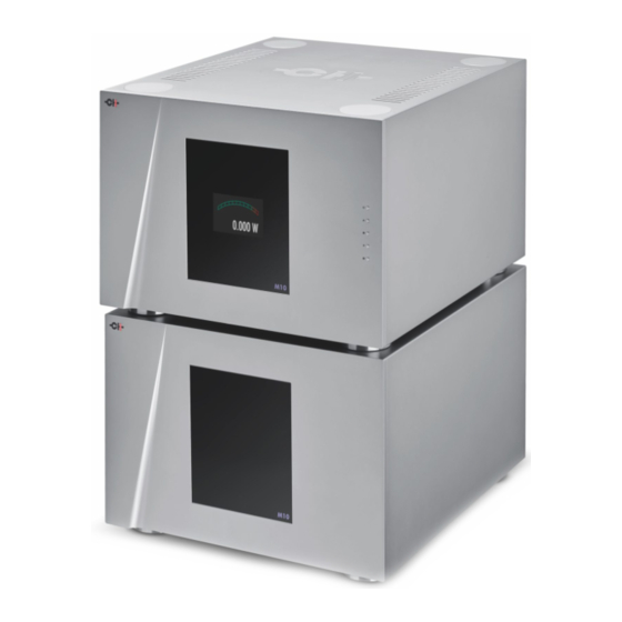
- Page 1 M10 Two-Channel Reference Power Amplifier User Manual...
- Page 2 Power Amplifier. Our team has made every effort in the design and manufacture of this top quality versatile and future-proof product and is proud to present it to you. We hope your M10 amplifier will bring you uncountable hours of emotional connection with your music collection.
-
Page 3: Table Of Contents
2.6.1 USB port 2.6.2 Ethernet port 2.6.3 Local area network considerations 2.6.4 Ground lift 2.6.5 Inputs 2.6.6 Outputs 2.6.7 AC Power How to configure and operate your M10 Front panel controls Normal mode Shortcuts Menu mode Menu options 3.5.1 Audio settings menu 3.5.2 Input-specific settings menu... -
Page 4: Introduction
As a result, your M10 offers a number of operational features that are unique and probably unfamiliar. For that reason it is essential that you fully understand every aspect of the M10’s operation if you are to enjoy its maximum possible performance. -
Page 5: More User Configurable Options
If you take the time to follow the manual, it will ensure that you become completely familiar with the M10’s many options and that your amplifier delivers the best possible performance. M10 User Manual... -
Page 6: Setting Up Your M10
With a helper, carefully lift the M10 component out of the box and place it to one side. Then carefully remove the plastic bag in which it is sealed. Alternatively, open the carton, fold the flaps out of the way and gently turn the whole box over. -
Page 7: Package Contents
If you do plan to use the CH spikes, use the blue suction cup to lift the four magnetic circular covers in the top plate of each unit. Gently insert the titanium composite spikes into each exposed shaft and use the short red screwdriver to turn them enough to engage the threads at the bottom of each spike. - Page 8 This should ensure that the load is evenly applied on all four spikes. It is worth using a spirit level to ensure that the M10 units are perfectly level. If they are not at this point of the setup, adjust the spikes with the screwdriver.
-
Page 9: Stacking The M10 (Or Not)
Also included in the accessory packs is a set of small, dimpled stacking caps for each unit. These polymer inserts allow owners to stack the M10 units on top of each other. However, this will inevitably compromise performance and should only be done when space is at an absolute premium. -
Page 10: Connections
2.6 Connections With the two (or four) M10 units placed and levelled, you are now ready to connect your signal cables. The rear panel layout is shown below: 10 12 M10 audio unit rear panel connections 1. Right channel negative loudspeaker terminal #2 13. - Page 11 M10 power supply unit rear panel connections 1. Control (digital) power supply umbilical cable, 7. Earth socket. Internally connected to digital to be connected to the corresponding socket in ground and chassis the audio unit 8. Mains voltage selector. Make sure it matches 2.
-
Page 12: Usb Port
(DC to 500 kHz) amplifier such as the M10 is used. To overcome this issue, the bandwidth of the M10 can be limited to 120 kHz thanks to a low pass filter that can be activated independently for any of its input. This low-pass filter is not recommended with analog sources nor with CH Precision DACs. -
Page 13: Outputs
With all the signal inputs and outputs connected, you can now connect the two 20A IEC power cords to the input sockets on the M10 power supply and switch the units on. You should see the red bar in the CH logo in the top-left corner of each front panel illuminate. -
Page 14: How To Configure And Operate Your M10
3 How to configure and operate your M10 The M10 amplifier is operated either from the unit’s front panel display and push buttons or from the CH Control app. The initial set up should be done using the front panel buttons and the menus shown on the display. -
Page 15: Normal Mode
The push buttons located on the front panel of the M10 allow users to operate the amplifier as well as configure its various selectable parameters. Button position Button symbol Description 1st (top position) Standby (long push), Mute/Unmute (short push) Down... -
Page 16: Shortcuts
(in Watts) supplied to the loudspeaker 3.3 Shortcuts The M10 amplifier settings are accessible through menus accessed via the five control buttons (or via the CH Control app) and viewed on the display. The amplifier also offers Shortcuts to the most frequently used configuration menu items. -
Page 17: Menu Mode
3.4 Menu mode The Menu mode allows the configuration and set up of the M10 amplifier. Menu mode is entered by pressing the OK [ ] button until DETAILED SETUP appears on the main display. Then press UP [ ] to actually access the available menus. - Page 18 M10 amplifier menu structure Normal mode BI-AMP ENTER Shortcut mode SHORTCUT 1 SHORTCUT 2 SHORTCUT N EXIT Menu mode M10 SETUP >> AUDIO >> M10 SETUP AUDIO AMPLIFIER MODE AUDIO >> GLOBAL FEEDBACK M10 SETUP >> INPUTS >> AUDIO >>...
-
Page 19: Audio Settings Menu
Allows users to select between the different operating modes (stereo, active/passive bi-amp, monaural or bridged). With a single M10, you can only use the amplifier in stereo mode. However, with a pair of M10s there is a range of possible options, generally dictated by the matching speakers. -
Page 20: Input-Specific Settings Menu
It should only be used if noise floor is an audible problem. Low-pass filter The default bandwidth of the M10 is DC to 500 kHz. As some delta-sigma DACs with little output filtering can generate high frequency content that may damage loudspeaker tweeters when amplified by a wide bandwidth system, we provide the facility to add a low pass filter with a cutoff frequency of 120 kHz in the amplifier’s signal path. -
Page 21: Shortcut Menu
If Yes is selected, the M10 will enter standby mode when it receives a Power Off command from the LAN. It will remain on if No is selected. This is useful if you want to keep your M10 on even when you turn off the rest of your system. -
Page 22: Factory Settings Menu
3.5.6 Factory settings menu Serial number Displays the serial number of your M10. This serial number is also written on a sticker at the back of your M10. Firmware version Indicates the version of the firmware that the M10 is currently running. Periodically check CH Precision’s website to see if a newer version is available. -
Page 23: Firmware Update
4.1 Preparing the USB stick The firmware of all the CH Precision units can be updated using the USB port located at the back of the unit. Before starting the firmware update, it is necessary to load a USB stick with files containing the new firmware. -
Page 24: Emergency Firmware Update Procedure
5. If the emergency firmware update procedure fails, try the same procedure again using a different USB stick. If the failure persists, turn off your unit and contact your authorized dealer for assistance. Note: The emergency firmware update procedure lasts 5-10 minutes, do NOT interrupt it! M10 User Manual... -
Page 25: Troubleshooting
Never try to reconnect an umbilical power cable or the mains power cable while your M10 is not fully off. If any power cable gets disconnected by mistake while your M10 is on, just let it safely automatically turn off. Do not try to interfere with the emergency power down procedure of the device. -
Page 26: Specifications
Dimensions of each chassis (WxDxH) 440mm x 500mm x 272mm (main body) 440mm x 560mm x 285mm (overall, including connectors and feet) Weight Audio unit: 53kg Power supply unit: 78 kg Software update USB port for software update / Ethernet based system control M10 User Manual... - Page 27 Design and Specifications are subject to change without notice. Weight and dimensions are approximate. Illustrations are informative only and may differ from the actual production model. Enclosure designed by Momentum Industrial Design – www.momentum.ch FCC-Notice Note: This equipment has been tested and found to comply with the limits for a Class B digital device, pursuant to Part 15 of the FCC Rules.
Need help?
Do you have a question about the M10 and is the answer not in the manual?
Questions and answers