Advertisement
Quick Links
1
3 D H O B B Y S H O P . C O M
Assembly Manual
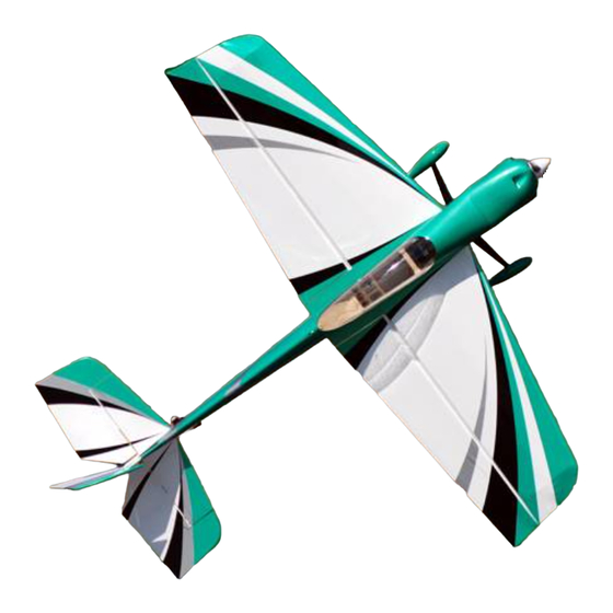
Vyper 46" ARF
Thank you for purchasing this 3DHobbyShop ARF RC aircraft. If you have any issues, questions,
concerns or problems during assembly, please contact our tech department at:
Info@3DHobbyShop.com
or 1-830-990-6978 10am-5pm Central M-F
We highly recommend
www.RCGroups.com
as a good source for RC tips, tricks, and information.
SAFETY in Assembly
During assembly of this aircraft, you will be asked to use sharp knives and hobby adhesives. Please
follow all safety procedures recommended by the manufacturers of the products you use, and always
follow these important guidelines:
ALWAYS protect your eyes when working with adhesives, knives, or tools, especially power tools. Safety
glasses are the best way to protect your eyes.
ALWAYS protect your body, especially your hands and fingers when using adhesives, knives, or tools,
especially power tools. Do not cut toward exposed skin with hobby knives. Do not place hobby knives on
tables or benches where they can roll off or be knocked off.
ALWAYS have a first-aid kit handy when working with adhesives, knives, or tools, especially power tools.
ALWAYS keep hobby equipment and supplies out of the reach of children.
IMPORTANT NOTE – We strive to provide the absolute best-quality ARF aircraft on the planet. However,
the ultimate success or failure of this aircraft is dependent upon proper assembly by you. If you have
questions about an assembly step, please contact us, or read the assembly thread for your airplane on
RCGroups.com before proceeding. It is always better to slow down and be sure of your assembly than to
rush through it and make a mistake which can cause a crash.
SAFETY in Flying
SAFETY NOTICE: This is NOT a toy! It is a very high-performance RC airplane capable of high speeds
and extreme maneuvers. It should only be operated by a competent pilot in a safe area with proper
supervision.
ONLY fly your aircraft in a safe, open area, away from spectators and vehicles–and where it is legal to fly.
NEVER fly over an unsafe area, such as a road or street.
NEVER fly near overhead power or utility lines. If your airplane ever becomes stuck in a line or a tree DO
NOT attempt to retrieve it yourself. Contact the authorities for assistance in retrieving your aircraft.
Power lines are DANGEROUS and falls from ladders and trees CAN KILL!
Never fly too close to yourself or spectators. Spinning propellers are DANGEROUS!
Never run your motor inside a house or building with the propeller attached – Remove the prop for safety.
Always fly within your control.
Advertisement

Related Manuals for 3DHobbyShop.com Vyper 46” ARF

Summary of Contents for 3DHobbyShop.com Vyper 46” ARF
- Page 1 Assembly Manual Vyper 46” ARF Thank you for purchasing this 3DHobbyShop ARF RC aircraft. If you have any issues, questions, concerns or problems during assembly, please contact our tech department at: Info@3DHobbyShop.com or 1-830-990-6978 10am-5pm Central M-F We highly recommend www.RCGroups.com as a good source for RC tips, tricks, and information.
-
Page 2: Required Items
Always follow manufacturer’s instructions for your radio system. Always obtain proper insurance before flying – contact the AMA at www.modelaircraft.org REQUIRED ITEMS CA Glue – Thin and Thick Hobby Knife Small Phillips Screwdriver Set Metric Allen Wrenches Scissors Small Pliers Wire Cutters Masking tape Optional –... - Page 3 ASSEMBLY Locate the wheels, wheel axles and axle nuts, wheel collars, and wheel pants. Fit the wheel onto the axle. Install the wheel collar to retain the wheel onto the axle, as shown. Slide the wheel/axle assembly into the wheel pant. Use the axle nut to affix the wheel/axle/pant assembly onto the gear leg, as shown.
- Page 4 Remove the covering on both sides of the fuselage as shown, for the wing spar tube, aileron wire access, wing retaining screw, and anti-rotation pin. Use either a sharp hobby knife or hot soldering iron to cut the covering away. Also remove the covering over the horizontal stabilizer slot as shown, on both sides.
- Page 5 Slide the horizontal stabilizer into the fuselage cutout and center it side-to-side, measuring with a ruler. Locate the carbon wing-spar tube. Slide it into the fuselage and slide the wings on as shown. Measure as shown with a tape measure or yardstick to ensure that the stabilizer is straight. Both sides should measure exactly the same.
- Page 6 Slide the right side elevator onto the stabilizer, inserting the fiberglass joiner strip through the fuselage cutout as shown – DO NOT GLUE THE HINGES YET. Slide the left elevator onto the stabilizer, gluing the fiberglass joiner strip in with medium or thick CA – DO NOT GLUE THE HINGES YET.
- Page 7 Using your hobby knife, remove the covering on the bottom of the rudder over the tailwheel wire slot. Using the end of a small screwdriver, or a small drill bit, make the necessary hole for the bent-portion of the tailwheel wire so that the pivot of the tailwheel is exactly in-line with the rudder hinges. Glue the tailwheel wire into the rudder with thick CA as shown.
- Page 8 FUSELAGE FRONT ASSEMBLY Take THIN CA glue and go over the motor mount area and landing-gear mount area, applying a small amount of glue to all the seams. This is the highest-stress area of the airframe, and we want to make it as strong as possible.
- Page 9 Install motor with the longer 3mm screws as shown. Please note that the motor is installed IN FRONT of the firewall. NOTE: Your kit contains 4 plastic motor mount spacers. They may be used as shown to space the motor away from the firewall as needed for cowl clearance.
- Page 10 Assemble the pushrods for the elevator and ailerons as shown. The longest pushrod in the kit is for the push-pull rudder and is used in only some applications, which will be mentioned later. Attach the ball links to the control horns as shown using 2mm screws, washers and nuts. Tighten the nuts, then apply a drop of CA to each nut to lock it into place so that it cannot come loose.
- Page 11 Assemble the ailerons onto the wings, flex them up and down to check for free motion, and drip thin CA glue onto each hinge. Allow to dry. Remove the covering over the aileron servo openings and aileron control horn slots as shown. Mount servo as shown.
- Page 12 NOTE – RUDDER SERVO LOCATION The Vyper can use two types of power systems, lightweight 3S lipo systems and heavier 4S lipo systems. For the lighter 3S systems, use the pull-pull rudder system with the servo mounted under the canopy. For heavier 4S systems, use the rear-mount push-pull system with the steel pushrod.
- Page 13 Please examine the pull-pull system assembly diagram closely: When attaching the servo connectors to the arm, do not tighten the nut fully, but leave it a bit loose so the connectors can rotate freely. Use a drop of CA glue on the nut to prevent it from loosening in flight. Start by attaching the cables to the pull-wire end.
- Page 14 Feed the cables through the slots into the fuselage and route them forwards to the rudder servo location. They cross over each other to form an X before they reach the rudder servo. Mount the rudder servo as shown. Install the rudder servo arm, and spend time to find the exact correct length of the pull-pull wires before attaching the pull wire ends at the front.
- Page 15 REAR-MOUNT Servo Installation For the rear-mount rudder servo location, remove the covering and install the servo in the bottom rear of the fuselage as shown. Assemble the rudder pushrod and control horn as shown: Be sure to use CA glue to lock the 2mm nuts so they do not come loose in flight. Install the rudder horn into the rudder with medium or thick CA and attach the pushrod to the servo arm as shown.
- Page 16 Remove the covering over one of the open bays in the bottom of the fuselage for battery/motor cooling.
- Page 17 Mount the receiver either to the fuselage side or to the balsa piece marked “Rx” and glue into fuselage. Mount the lipo battery to the battery tray using the included Velcro strip and Velcro “seatbelt” strap as shown. Plug your servos and ESC into your receiver, attach your battery and test your radio system. Check for correct motor running direction now, before your prop is installed.
- Page 18 Scott’s Tip: Control Throws and Exponential Setting appropriate control throws is a critical step in matching your model to your flying style. Personally, I use two different flight “modes”– precision and 3D. Depending upon your radio, you may be able to combine all three dual rate functions onto a single switch, which is the technique I use.
- Page 19 your flights and keep them a bit shorter than usual. After your first flights, check all control connections and motor and prop mounts for tightness. If using rudder pull-pull cables, check your rudder pull-pull cables for tightness at the beginning of each flying session.
Need help?
Do you have a question about the Vyper 46” ARF and is the answer not in the manual?
Questions and answers