Table of Contents
Advertisement
Quick Links
Advertisement
Table of Contents

Summary of Contents for Anaheim Automation MBC25P11
- Page 1 MBC25P11 Programmable Pulse Generator/Driver User’s Guide A N A H E I M A U T O M A T I O N 4985 E. Landon Drive Anaheim, CA 92807 (714) 992-6990 fax: (714) 992-0471 e-mail: info@anaheimautomation.com website: www.anaheimautomation.com July 2018...
-
Page 2: Table Of Contents
Table of Contents Features ..............................3 Introduction ............................... 3 Motion Profiles and Running the Pulse Generator ................... 3 Operation with Ramp Down Option ......................4 Operation without Ramp Down Option ..................... 4 Operation with Soft and Hard Limits ......................4 LEDs ................................. -
Page 3: Features
35VDC. The MBC25P11’s internal PG (pulse generator) has four different programmable motion profiles. The MBC25P11 also has directional soft and hard limit switch inputs, a busy output and a clock output that can be used for daisy chaining drivers together. The MBC25P11 driver features direction control and motor current On/Off capabilities. -
Page 4: Operation With Ramp Down Option
Operation with Ramp Down Option A) Run is activated; Starts at base speed and immediately ramps up to max speed. B) Run is still active; Max speed is reached (keeps running at max speed). C) Run is inactivated; Motor ramps down. D) Pulses automatically stop when base speed is reached. -
Page 5: Leds
LEDs When powered and operated properly, the status LED will be green. When an error occurs, the LED will change to RED and an error code will be generated in the error code register. To read and clear the error with the software, click on the “Verify Parameters”... -
Page 6: Connector Descriptions
Hard Limits: These two inputs are active low and are controlled by the direction of the pulse generator. When the pulse generator is running in the positive direction only hard+ will work. When the pulse generator is running in the negative direction then only hard- will work. When pulled low the pulse generator will stop all pulses to the motor. -
Page 7: Ordering Information
Description MBC25P11 2.5A Microstep Driver with integrated Programmable Pulse Generator PSAM24V2.7A Power supply for MBC25P11 (24V@2.7A) CON-6404287 Optional 7 pin connector, 0.156" IDC (AMP part no. 640428-7) CON-6404289 Optional 9 pin connector, 0.156" IDC (AMP part no. 640428-9) CON-16404280 Optional 10 pin connector, 0.156" IDC (AMP part no. 1-640428-0) -
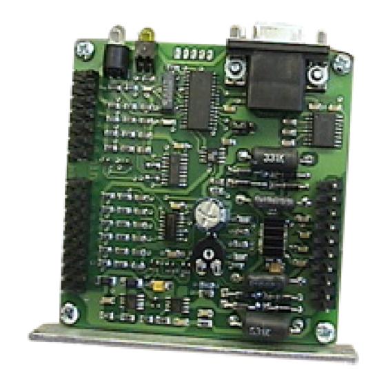
Page 8: Dimensions And Jumper/Potentiometer Locations
Dimensions and Jumper/Potentiometer Locations Wiring Diagrams Two Motors One Motor #L010128 June 2002 July 2018... -
Page 9: Jumper Functions
(1,2,4, or 8). (Refer to Motion Tab Sheet) Setting the Output Current The output current on the MBC25P11 is set by the on-board potentiometer R29 (Refer to Dimensions/ Jumper and Potentiometer Locations). This current adjust potentiometer determines the per phase peak output current of the driver. -
Page 10: Determining Output Current
The output current used for the motor when microstepping is determined differently from that of a full/half step unipolar driver. In the MBC25P11, a sine/cosine output function is used in rotating the motor. The output current for a given motor is determined by the motors current rating and the wiring configuration of the motor. -
Page 11: Connecting The Step Motor
Connecting the Step Motor The MBC25P11 is designed to accept either one or two motors. For wiring of the motor refer to the pages containg the connector descriptions and hookup diagrams. -
Page 12: Functions
Functions Hard Limit Switches: When a hard limit switch is encountered, the pulses will stop. Hard limits are in- tended as an emergency stop for your system. Soft Limit Switches: These switches cause the pulse generator to ramp down to the base speed before encountering a hard limit switch. -
Page 13: Smpg10Win Software
SMPG10WIN Software The SMPG10WIN software is a handy utility that supports Anaheim Automation’s programmable pulse generator. Connecting your PC to the MBC25P11, via a serial cable, the SMPG10WIN software can eas- ily perform the following tasks: • Exercise and monitor the MBC25P11 •... -
Page 14: The Unit Is Connected" / "The Unit Is Not Connected
“The Unit is Connected” / “The Unit is NOT Connected” On the right of the Toolbar, the user will find the communication status of the pulse generator. If commu- nications is not established, please refer to the troubleshooting section. File Menu Setup Menu Exit Exit the SMPG10WIN software... -
Page 15: Program Window
Program Window Speed Profile Select speed profiles 1-4. Send acceleration & deceleration parameter to the pulse generator. (1=fastest, Send Accel/Decel 255=slowest) Send Base Speed Send base speed parameter to the pulse generator. (step/sec) Send Max Speed Send maximum speed parameter to the pulse generator. (step/sec) Begin Motion Motor will ramp up to maximum speed and keep moving until a limit switch is triggered. -
Page 16: Direct Talk Mode
Direct Talk Mode Direct mode is used to directly control the motion for real time movements through serial communication. The pulse generator has 14 commands which are easy to remember for direct movement of a step motor. COM Port Settings Baud Rate: 9600 Parity:... - Page 17 $ - Version Number Register Format : Description: This command requests the pulse generator to return the version number. ! - Error Codes Register Format : Description: This command requests the pulse generator to get the current error code and print it to the screen.
- Page 18 D - Decceleration Option Format: D# - where # is 0 or 1 Description: This command enables the pulse generator to ramp down to base speed before stopping when using the external Run/Stop input. A 1 will enable the pulses to ramp down to base speed and stop, and a 0 will disable ramp down causing the pulse generator to hard stop at maximum speed.
- Page 19 V - Verify Description: This command can be used with most commands to verify the register contents. This is a read only command. Valid Commands are: A, B, C, D, M, R, and +. Format: V[command] This format is good for C, D, R, and +. If a 1 is sent back then the driver is in reduced current mode.
-
Page 20: Troubleshooting
5) Go to Setup | Communication Settings and verify COM port and baud rate settings. 6) Click on Connect icon to communicate with the pulse generator. 9) If problems still exist, contact Anaheim Automation Tech Support. Problem: There is no power to the pulse generator. -
Page 21: Error Codes
Error Codes Error Type Description Code The serial communications had a recieving error. This is an internal error caused Recieve Overflow Error by the computer. There was an invalid number of characters sent to the pulse generator. Check to Range Error see if the parameters are invalid for the command that was sent. -
Page 22: Torque Speed Curves
Anaheim Automation will repair or replace at its option, any of its products which have been found to be defective and are within the warranty period, provided that the item is shipped freight prepaid, with RMA (return material authorization), to Anaheim Automation’s plant in Anaheim, California.
Need help?
Do you have a question about the MBC25P11 and is the answer not in the manual?
Questions and answers