
Summary of Contents for Vertilon SIB916
- Page 1 User Guide SIB916 4 x 4 SiPM Sensor Interface Board Broadcom AFBR-S4N44P163 Vertilon Corporation, 66 Tadmuck Road, Westford, MA 01886 Tel: (978) 692-7070 Fax: (978) 692-7010 www.vertilon.com...
- Page 3 Vertilon reserves the right to change this product without prior notice. No responsibility is assumed by Vertilon for any infringements of patents or other rights of third parties which may result from its use. No license is granted by implication or otherwise under the patent and proprietary information rights of Vertilon Corporation.
- Page 4 SIB916 Sensor Interface Board for Broadcom AFBR-S4N44P163 - 2 - Vertilon Corporation, 66 Tadmuck Road, Westford, MA 01886 Tel: (978) 692-7070 Fax: (978) 692-7010 www.vertilon.com...
-
Page 5: Table Of Contents
Temperature Sensor ..........................16 Top / Bottom Views ..........................17 Component Locations and Functions....................18 SIB Connector Pinout ..........................20 Mechanical Information .......................... 21 - 3 - Vertilon Corporation, 66 Tadmuck Road, Westford, MA 01886 Tel: (978) 692-7070 info@vertilon.com www.vertilon.com... - Page 6 Figure 10: Minimum Pulse Width Condition ..................... 16 Figure 11: PCB Top and Bottom Views ....................17 Figure 12: Top Component Locations and Functions ................18 Figure 13: SIB916 Printed Circuit Board Dimensions ................21 List of Tables Table 1: Specifications ..........................8 Table 2: SiPM Array Channel Mapping ....................
-
Page 7: General Safety Precautions
A separate negative power source from the PhotoniQ is used to generate the high voltage bias signal to the SiPM array. Use with any other power sources may result in damage to the SIB916 or the SiPM array. Operate Inputs within Specified Range To avoid electric shock, fire hazard, or damage to the product, do not apply a voltage to any input outside of its specified range. -
Page 8: Product Overview
PhotoniQ graphical user interface. A special current-sense output from the bias interface circuitry is routed to the input of a variable gain preamplifier on the SIB916 to represent the total AC current signal to all 16 SiPM channels. This signal, which is available to the user on an SMB jack, is fed into a leading edge discriminator with a user-programmable threshold. -
Page 9: Figure 1: Functional Block Diagram
INPUT B INTERFACE INT B BROADCOM AFBR-S4N44P163 4 x 4 SiPM ARRAY VERTILON SIB916 AFBR-S4N44P163 SiPM SENSOR INTERFACE BOARD Figure 1: Functional Block Diagram - 7 - Vertilon Corporation, 66 Tadmuck Road, Westford, MA 01886 Tel: (978) 692-7070 info@vertilon.com www.vertilon.com... -
Page 10: Specifications
SIB916 Sensor Interface Board for Broadcom AFBR-S4N44P163 Specifications = +25C, unless otherwise noted) Description Units Notes INPUT CHANNELS Quantity 16 direct coupled channels to PhotoniQ channels 1 to 16. Detector cathode voltage supplied from PhotoniQ data Cathode Bias Voltage +0.25... -
Page 11: Typical Dual Sensor Setup
The Broadcom AFBR-S4N44P163 4 x 4 SiPM arrays are mounted to the SIB916s which are positioned in an optical assembly to detect incoming radiation. The SIB cables from each SIB916 connect to a Vertilon SIB1632 where the 16 outputs from each SiPM array are combined into one SIB cable (SBC090) that connects to a PhotoniQ IQSP480 or IQSP580 multichannel data acquisition system. -
Page 12: Detector Channels
The PhotoniQ utilizes DC-coupled high speed transimpedance amplifiers that maintain a DC bias voltage of +0.250 volts on each of its inputs. Because the AFBR-S4N44P163 is configured on the SIB916 as a common anode type, the current polarity to the PhotoniQ preamplifiers is out of the inputs. For this reason, the Input Polarity under the Data Configuration menu in the PhotoniQ GUI should be set to positive. -
Page 13: Detector Channel Mapping
Detector Channel Mapping The 16 SiPM channels from the AFBR-S4N44P163 are labeled in Broadcom’s datasheet as channels A1 through D4. These channels map to Vertilon’s PhotoniQ data acquisition system channels according to the table below. Figure 5: Bottom Component Locations and Functions... -
Page 14: High Voltage Interface
High Voltage Interface The SIB916 employs the interface circuit shown below between the high voltage input connector, J8, and the common anodes of the SiPM array. The monitor output (HVMON) allows the high voltage anode bias to the SiPMs to be indirectly monitored at a reduced voltage level. -
Page 15: Preamplifier
SIB916. The preamplifier generates a voltage signal in response to the current signal on its input from any of the 16 SiPMs in the array. This voltage signal is available on an SMB output connector on the SIB916 and is also fed to the input of the discriminator. -
Page 16: Discriminator
The discriminator generates a logic signal when a pulse from the preamplifier exceeds a user-defined threshold. The SIB916 PhotoniQ GUI dialog box allows the user to enable and disable the discriminator and set its threshold. The threshold range is between a lower limit and 100% of the maximum possible signal amplitude in the preamplifier signal path. -
Page 17: Coincidence Detector
The SIB916 includes a two input configurable coincidence detector that can be used with the on-board discriminator or in a stand-alone mode. In a typical setup using two SIB916 (referred to here as the master and slave units), both boards are configured identically except that the master employs its coincidence detector and the slave unit’s coincidence detector is... -
Page 18: Trigger Output
Temperature Sensor An on-board temperature sensor is located on the bottom side of the SIB916 near the SiPM array. The sensor reports the temperature of the circuit board in degrees Celsius to the PhotoniQ graphical user interface. This information is useful for determining the proper bias to the SiPM array. -
Page 19: Top / Bottom Views
11. Test Input Jack (Factory Use Only) SiPM Negative Bias Input (J8) 12. Temperature Sensor Trigger Status LED 13. Mounting Nuts Preamplifier Output (J7) - 17 - Vertilon Corporation, 66 Tadmuck Road, Westford, MA 01886 Tel: (978) 692-7070 info@vertilon.com www.vertilon.com... -
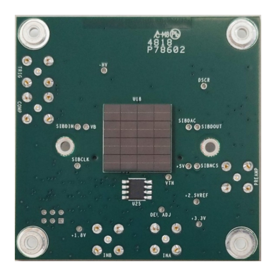
Page 20: Component Locations And Functions
SIB916 Sensor Interface Board for Broadcom AFBR-S4N44P163 Component Locations and Functions 2 3 4 Figure 12: Top Component Locations and Functions - 18 - Vertilon Corporation, 66 Tadmuck Road, Westford, MA 01886 Tel: (978) 692-7070 Fax: (978) 692-7010 www.vertilon.com... -
Page 21: Table 3: Connectors
Test input (for factory use only) Table 3: Connectors Name Function Description STATUS Bicolor (red/yellow/green) LED indicator for SIB916 status. SW1: 1-2 DEV ADDR 1:0 Sets the device address for control by the PhotoniQ. Set both switches to “ON”. SW1: 3-4 DEV TYPE 1:0 Sets the device type for control by the PhotoniQ. -
Page 22: Sib Connector Pinout
SIB Connector Pinout The SIB916 connectors and cables are fully compatible with all Vertilon PhotoniQ systems. For applications utilizing data acquisition systems other than Vertilon’s PhotoniQ series, the pinout for connector J5 is provided in Table 6 as a reference. -
Page 23: Mechanical Information
4.20 2 3 4 57.40 PEM mounting nut, #4-40, bottom side mount, 4pl. ALL DIMENSIONS IN MILLIMETER Figure 13: SIB916 Printed Circuit Board Dimensions - 21 - Vertilon Corporation, 66 Tadmuck Road, Westford, MA 01886 Tel: (978) 692-7070 info@vertilon.com www.vertilon.com... - Page 24 Vertilon reserves the right to change this product without prior notice. No responsibility is assumed by Vertilon for any infringements of patents or other rights of third parties which may result from its use.
Need help?
Do you have a question about the SIB916 and is the answer not in the manual?
Questions and answers