Advertisement
Quick Links
INSTRUCTION SUPPLEMENT
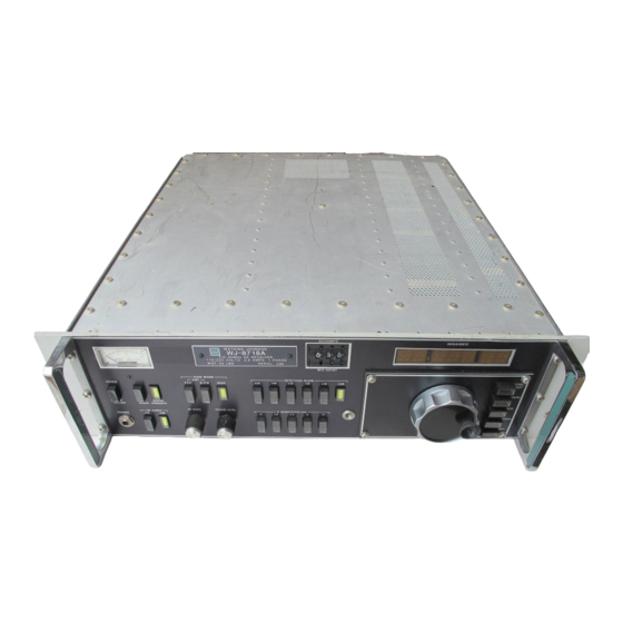
WJ-8718A AND WJ-8718A/MFP
1-Hz READOUT OPTION
(TENTATIVE MANUAL)
This
document
disclosed
herein
which
Watkins-Johnson
exclusive right of dissemination, reproduction,
manufacture and sale.
This document is provided to the individual or
using organization for their use alone in the
direct support of the associated equipment
unless
permission
expressly granted in writing.
WATKINS-JOHNSON COMPANY
700 QUINCE ORCHARD ROAD
GAITHERSBURG MARYLAND 20878
FOR
and
the
subject
are
proprietary
items
Company
retains
for
further
disclosure
1
matter
to
the
is
Advertisement

Related Manuals for Watkins-Johnson Company WJ-8718A

Summary of Contents for Watkins-Johnson Company WJ-8718A
- Page 1 INSTRUCTION SUPPLEMENT WJ-8718A AND WJ-8718A/MFP 1-Hz READOUT OPTION (TENTATIVE MANUAL) This document subject matter disclosed herein proprietary items which Watkins-Johnson Company retains exclusive right of dissemination, reproduction, manufacture and sale. This document is provided to the individual or using organization for their use alone in the...
- Page 2 NOTICE This is not the original Instruction Manual for the 1- Hz Option for the WJ-8718A Receiver Series, it is only an attempt to write one from scratch. It is based upon visual inspection and visual circuit tracing on existing and unmodified WJ-8718A and WJ-8718A/MFP receivers including this rare option.
- Page 3 The following tools are necessary to perform the modification steps: Phillips screwdriver; Soldering gun and solder. Perform the following steps to install the 1-Hz Option in the WJ-8718A or in the WJ-8718A/MFP receiver: 1. Remove power from the unit. 2. Remove top and bottom covers from the unit.
- Page 4 PTFE-insulated stranded wires and standard strip-line female connectors that have to be inserted into the proper socket pins. In this case, two four-pole female connectors are required for the WJ-8718A, a four- pole and three two-pole female connectors are required for the WJ-...
- Page 5 Figure 1a: A6 I/O mainboard of a WJ-8718A 1-Hz resolution receiver (bottom side). Figure 1b: Further details of the same WJ-8718A receiver (A6 I/O MB, bottom side).
- Page 6 Figure 2: A6 I/O mainboard of a WJ-8718A/MFP 1-Hz resolution receiver (bottom side). Figure 3: Factory-installed wire-wrap wiring for the 1-Hz Option in a WJ-8718A/MFP radio (A6 I/O mainboard partial view, bottom side).
- Page 7 Figure 4: Alternative wiring on the A6 I/O MB for the 1-Hz option in a WJ-8718A and in a WJ-8718A/MFP. Some strip-line female connectors and stranded wires are used. 8. Final steps: For receivers with Manual Tuning Module only (WJ-8718A etc.): Locate the A6A1 Manual Tuning Up-Down Counter card (791575-X) on the A6 I/O mainboard, sockets XA1 (X7 and X8);...
- Page 8 Figure 4a: A 796014 card that replaces the stock 791575-X board (front view). Figure 4b: Rear view of a 796014 card. For receivers already having an MFP front panel (WJ-8718A/MFP, etc.): Locate the MFP-A4 Synthesizer Interface/Memory card (794275-X) on the A6 I/O mainboard, sockets XA1 (X7 and X8); unplug and remove it,...
- Page 9 Figures 5(a-b): A 794275-X MFP-A4 card suitable for the 1-Hz Option: notice the presence of U17 (normally missing) and of two EPROMS (U1 and U2) that include the 1-Hz software (front and rear views). Figure 5c: Details of U17 connections (wire bridges in the front of the MFP-A4 card)
- Page 10 Figure 5d: Details of U17 connections (wire bridge in the rear of the MFP-A4 card) Figure 6: Schematic detail of the PCB bridges near U17 For all receivers: Install the new front panel using the same six screws removed in step (3) above;...
- Page 11 Figure 7a: The 796022 1-Hz Option card for the WJ-8718 Series of receivers (front side).
- Page 12 Figure 7b: The rear (shielded) side of the same 796022 1-Hz Option card.
- Page 13 WJ-8718A & WJ-8718A/MFP 1-Hz OPTION PRINCIPLES OF OPERATION AND CIRCUIT DESCRIPTION In stock receivers (10-Hz tuning resolution) the coaxial cable bridge named W6 and placed on the bottom side of the receiver - towards the rear of the unit and in correspondence of the A6 I/O mainboard - leads the 11.155,000 MHz signal coming from the third L.O.