
Subscribe to Our Youtube Channel
Summary of Contents for SIGNALCORE SC5412A
- Page 1 SC5412A 400 MHz to 6 GHz IQ Modulator PXI Express Interface Operating and Programming Manual © 2013-2020 SignalCore, Inc. support@signalcore.com...
-
Page 2: Table Of Contents
Warnings Regarding Use of SignalCore Products ................... 3 Getting Started Unpacking ............................... 4 Verifying the Contents of your Shipment ....................4 Setting Up and Configuring the SC5412A ....................4 RF Signal Connections ........................6 Baseband Connections ........................7 Indicator LED ............................ 7 SC5412A Theory of Operation Overview .............................. - Page 3 Setting the Output Linearity of the IQ Modulator ................15 Storing the Startup State ........................15 Writing to the User EEPROM ........................ 15 Querying the SC5412A: Writing to Request Registers Reading the Device Temperature ......................16 Reading the Device Status ........................16 Reading the User EEPROM ........................
-
Page 4: Important Information
Please contact SignalCore if errors are suspected. In no event shall SignalCore be liable for any damages arising out of or related to this document or the information contained in it. -
Page 5: International Materials Declarations
SignalCore, Incorporated uses a fully RoHS compliant manufacturing process for our products. Therefore, SignalCore hereby declares that its products do not contain restricted materials as defined by European Union directive 2002/95/EC (EU RoHS) in any amounts higher than limits stated in the directive. -
Page 6: Warnings Regarding Use Of Signalcore Products
Warnings Regarding Use of SignalCore Products PRODUCTS FOR SALE BY SIGNALCORE, INCORPORATED ARE NOT DESIGNED WITH COMPONENTS NOR TESTED FOR A LEVEL OF RELIABILITY SUITABLE FOR USE IN OR IN CONNECTION WITH SURGICAL IMPLANTS OR AS CRITICAL COMPONENTS IN ANY LIFE SUPPORT SYSTEMS WHOSE FAILURE TO PERFORM CAN REASONABLY BE EXPECTED TO CAUSE SIGNIFICANT INJURY TO A HUMAN. -
Page 7: Getting Started
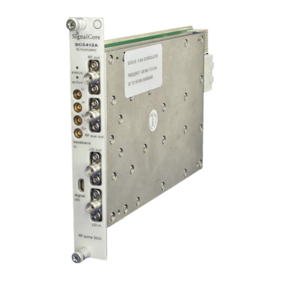
Getting Started Guide Setting Up and Configuring the SC5412A The SC5412A is a designed for use in a PXIe or PXIe hybrid chassis. Chassis manufacturers must provide at least the minimum required per-slot power dissipation cooling capability to be compliant with the PXIe specifications. - Page 8 The SC5412A is a PXIe-based IQ modulator with all I/O connections and indicators located on the front face of the module as shown below. Each location is discussed in further detail below. Figure 1. PXIe chassis view of the SC5412A. Module is shown installed in slot 2.
-
Page 9: Rf Signal Connections
All RF signal connections (ports) on the SC5412A are SMA-type. Exercise caution when fastening cables to the signal connections. Over-tightening any connection can cause permanent damage to the device. The condition of your system‘s signal connections can significantly affect measurement accuracy and repeatability. -
Page 10: Baseband Connections
All baseband connectors are MCX female. Indicator LED The SC5412A provides visual indication of important modes. There is one LED indicator on the unit. Its behavior under different operating conditions is shown in Table 1. Table 1. LED indicator states. -
Page 11: Sc5412A Theory Of Operation
SC5412A has the necessary RF amplifiers, attenuators and IF amplifiers to give the user optimal control of the device over the entire frequency range. Figure 3 shows a simplified block diagram of the SC5412A, showing only the signal conditioning components critical for the following discussion. The following sections provide more in-depth discussion on how to optimize the converter for linearity and signal- noise dynamic range. -
Page 12: Rf Output Section
15-16 dB. The RF amplifier has 14 dB of gain. If the overall gain is too excessive at the desired operating frequency, ATTEN#2 should be used to readjust the gain to the required level. SC5412A Operating & Programming Manual Rev 1.1.0... - Page 13 Figure 3. Simplified SC5412A block diagram. SC5412A Operating & Programming Manual Rev 1.1.0...
-
Page 14: Lo Input Section
IF bandwidth. A typical 1 dB IQ IF bandwidth is about 160 MHz. The user may want to choose a higher frequency filter if this becomes a problem. See the section “Setting the SC5412A: Writing to Configuration Registers” for more details. The filters in both the RF and LO filter banks are identical and are listed below. -
Page 15: Sc5412A Programming Interface
N T E R F A C E Device Drivers The SC5412A is programmed by writing to its set of configuration registers, and its data is read back through its set of query registers. The user may program directly at register level or through the API library functions provided. -
Page 16: Configuration Registers
DC_OFFSET_DAC 0x1A [15:8] DAC value [13:8] [23:16] Channel [7:0] DAC value [7:0] LINEARITY_DAC 0x1B [15:8] DAC value [13:8] [23:16] Channel STORE_STARTUP_STATE 0x1D [7:0] [7:0] Address [7:0] USER_EEPROM_WRITE 0x1F [15:8] Address [15:8] [23:16] Byte[7:0] SC5412A Operating & Programming Manual Rev 1.1.0... -
Page 17: Initializing The Device
RF_FILTER_SELECT (0x15) – There are 9 RF filters to select from to improve RF input second harmonic suppression. Bits [3:0] are used. Selecting the LO Filter LO_FILTER_SELECT (0x16) – There are 9 RF filters to select from to improve LO input second harmonic suppression. Bits [3:0] are used. SC5412A Operating & Programming Manual Rev 1.1.0... -
Page 18: Enabling Lo Output
The other two bytes contain the write address in the EEPROM. For example, to write user data 0x22 into address 0x1F00 requires writing 0x1F0022 to this register. SC5412A Operating & Programming Manual Rev 1.1.0... -
Page 19: Reading The Device Temperature
It is not recommended to read the temperature too frequently, especially once the temperature of the SC5412A has stabilized. The temperature sensor is a serial device located inside the RF module. Therefore, like any other serial device, reading the temperature sensor requires a sending serial clock and data commands from the processor. -
Page 20: Reading The User Eeprom
An example written in C code would look something like the following: byte_value[4]; // read in earlier unsigned int uint32_value; float float32_value; count while (count < 4) { uint32_value = unit32_value | (byte_value[count] << (count*8)); count++; float32_value = *(float *)&uint32_value; SC5412A Operating & Programming Manual Rev 1.1.0... -
Page 21: Calibration Eeprom Map
Table 5. Calibration EEPROM map. EEPROM NUMBER OF ADDRESS TYPE DESCRIPTION DATA POINTS (HEX) Manufacturing information Product serial number RF module number Product manufacture date Firmware revision Hardware revision Reserved Startup state Calibration temperature SC5412A Operating & Programming Manual Rev 1.1.0... -
Page 22: Software Api Library Functions
C/C++ is located in the CD:\Win\Driver\src directory to show how these functions are called and used. First, for C/C++, we define the constants and types which are contained in the C header file, sc5412a.h. These constants and types are useful not only as an include for developing user applications using the SC5412A API, but also for writing device drivers independent of those provided by SignalCore. -
Page 23: Constants Definitions
#define GET_TEMPERATURE 0x21 // get the internal temperature of the device #define USER_EEPROM_READ 0x23 // read a byte from the USER EEPROM #define CAL_EEPROM_READ 0x24 // read a byte from the calibration EEPROM SC5412A Operating & Programming Manual Rev 1.1.0... -
Page 24: Type Definitions
Function Definitions and Usage The functions listed below are found in the sc5412a.dll dynamic linked library for the Windows operating system. These functions are also provided in the LabVIEW library, sc5412a.llb. The LabVIEW functions contain context-sensitive help (Ctrl-H) to assist with understanding the input and output parameters. - Page 25 == 0) //If no device are found deallocate memory and end the program for(i = 0; i<10;i++) free(visaResource[i]); free(visaResource); printf("No sc5412a devices detected. Press enter to continue.\n"); return //** sc5412a_OpenDevice, open device 0 status = sc5412a_OpenDevice(visaResource[0], &deviceHandle); // Free memory for(i = 0;...
- Page 26 RF amplifier. Function: sc5412a_SetRfPath Definition: int sc5412a_SetRfPath(unsigned int deviceHandle, bool mode) Input: unsigned int deviceHandle (handle to the opened device) bool mode (0=main path, 1=aux path) Description: sc5412a_SetRfPath selects the RF input port. SC5412A Operating & Programming Manual Rev 1.1.0...
- Page 27 (DAC value range 0 - 16383) Description: sc5412a_SetDcOffsetDac sets the DC offset voltage at the IQ modulator core. Voltage adjust is approximately +/- 0.05 V. The default factory setting is 8038. SC5412A Operating & Programming Manual Rev 1.1.0...
- Page 28 *devInfo) Input: unsigned int deviceHandle (handle to the opened device) Output: deviceInfo_t *devInfo (device info struct) Description: sc5412a_GetDeviceInfo retrieves device information such as serial number, calibration date, revision, etc. SC5412A Operating & Programming Manual Rev 1.1.0...
- Page 29 (handle to the opened device) unsigned int memAdd (EEPROM memory address) Output: unsigned char *byteData (the read back byte data) Description: sc5412a_ReadUserEeprom reads back a byte from a specific memory address of the user EEPROM. SC5412A Operating & Programming Manual Rev 1.1.0...
- Page 30 A I N T E N A N C E The SC5412A does not receive a factory calibration. The SC5412A is sold as a component and users will need to perform amplitude and IQ correction as part of their system, which may minimally include a digitizer, LO source, and the SC5412A.
Need help?
Do you have a question about the SC5412A and is the answer not in the manual?
Questions and answers