
Related Manuals for SIGNALCORE SC5306B

Summary of Contents for SIGNALCORE SC5306B
- Page 1 SC5306B 1 MHz to 3.9 GHz RF Downconverter Core Module with USB and RS232/SPI Operating & Programming Manual © 2015-2020 SignalCore, Inc. support@signalcore.com SC5306B Operating & Programming Manual Rev 1.2...
- Page 2 SC5306B - Theory of Operation Overview Signal Path Description Local Oscillator Description Frequency Tuning Modes Setting the SC5306B to Achieve Best Dynamic Range Operating the SC5306B Outside Normal Range SC5306B Programming Interface Device Drivers The SC5306B USB Configuration Writing the Device Registers Directly...
- Page 3 Setting the SC5306B - Writing USB Configuration Registers Directly Configuration Registers Tuning the RF Frequency Changing the Attenuator Settings Enabling and Disabling the RF Preamplifier Changing the RF Synthesizer Mode Selecting the IF Filter Path Setting the Reference Clock Behavior...
- Page 4 Programming the SC5306B Serial Peripheral Interface The SPI Communication Connector The SC5306B SPI Architecture SPI Clock Rates and Modes Writing Configuration Data via the SPI Bus Reading Requested Data via the SPI Bus Calibration & Maintenance Revision Notes SC5306B Operating & Programming Manual Rev 1.2...
-
Page 5: Warranty
Please contact SignalCore if errors are suspected. In no event shall SignalCore be liable for any damages arising out of or related to this document or the information contained in it. -
Page 6: Copyright And Trademarks
SignalCore, Incorporated respects the intellectual property rights of others, and we ask those who use our products to do the same. Our products are protected by copyright and other intellectual property laws. Use of SignalCore products is restricted to applications that do not infringe on the intellectual property rights of others. -
Page 7: Recycling Information
Laboratory Equipment include EN 61326 and EN 55011 for EMC, and EN 61010-1 for product safety. Recycling Information All products sold by SignalCore eventually reach the end of their useful life. SignalCore complies with EU directive 2002/96/EC regarding Waste Electrical and Electronic Equipment (WEEE). -
Page 8: Getting Started
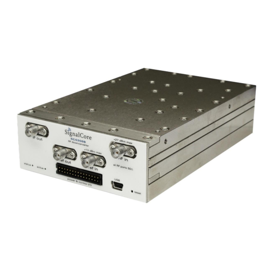
Figure 1. Front view of the SC5306B connectors. The SC5306B is a core module-based RF downconverter with all user I/O located on the front face of the module as shown in Figure 1. Each location is discussed in further detail below. - Page 9 Signal Connections All signal connections (ports) to the SC5306B are SMA-type. Exercise caution when fastening cables to the SMA connections. Over-tightening any connection can cause permanent damage to the device. The condition of your system‘s signal connections can significantly affect measurement accuracy and repeatability.
- Page 10 Reserved, pull high to 3.3V or RX/MOSI. This pin is RX for RS232 or MOSI for SPI RTS/SRDY. This pin is RTS for RS232 or , logic 0 to reset device Reset serial ready for SPI SC5306B Operating & Programming Manual Rev 1.2...
- Page 11 Device ground (also tied to connector shell) The SC5306B uses a mini-USB Type B connector for USB communication with the device using the standard USB 2.0 protocol (full speed) found on most host computers. The pinout of this connector, viewed from the board edge, is shown in the table above.
-
Page 12: Operation
P E R A T I O N Overview The SC5306B operates on the principle of heterodyning, a process whereby an incoming RF signal is mixed with specific oscillator frequencies in stages, producing both sum and difference frequency products. At each stage, the summed frequency product (or image) is removed through low-pass filtering, allowing the difference frequency product to continue through the signal path. - Page 13 The SC5306B exhibits very low phase noise of -107 dBc/Hz at 10 kHz offset on a 1 GHz RF carrier with a typical noise floor of -150 dBm/Hz. The noise floor can be further reduced below -165 dBm/Hz by enabling the internal preamplifier.
- Page 14 10 MHz Attenuator, ADC, DAC, other devices Ref. Out Power PXIe 10/100 MHz SPI, RS-232, USB Module A Regulation 3.9 GHz Three Stage Downconverter Figure 4. Block diagram of SignalCore 3.9 GHz downconverters. SC5306B Operating & Programming Manual Rev 1.2...
- Page 15 Finally, a low pass filter suppresses the harmonics of the IF signal. It is important that the IF harmonics are kept as low as possible because they appear in-band as higher order images SC5306B Operating & Programming Manual Rev 1.2...
- Page 16 RF, whereas the 605 MHz frequency will create an inverted IF spectrum. If LO3 is set to 605 MHz by calling the sc5306B_SetIfInversion function or register, the IF output spectral content will be inverted with respect to the input RF spectrum. See Figure 5 for a graphical representation of this process. SC5306B Operating & Programming Manual Rev 1.2...
- Page 17 10 MHz TCXO for frequency accuracy and stability. For better frequency accuracy and stability than the TCXO onboard the SC5306B or for frequency synchronization, the user can programmatically set the device to phase-lock the TCXO to an external 10 MHz reference source by programming the REFERENCE_SETTING register.
- Page 18 The SC5306B is designed for a nominal output IF level of 0 dBm, ensuring the IF signal is about 3-4 dB below the full-scale value of many 50 analog-to-digital data converters (ADCs). Depending on the application, the user will need to set the appropriate gain of the device (via attenuation), and hence the output level, to suit the particular application.
- Page 19 Operating the SC5306B Outside Normal Range The SC5306B is capable of tuning below 1 MHz and above 3.9 GHz. These frequencies lie outside of the specification range and performance will be degraded if operated in these outer margins. For some applications, the reduced dynamic range or elevated spurious levels in these ranges may not pose an application concern.
-
Page 20: Device Drivers
API other than that provided in the software installation, please contact SignalCore. The SC5306B USB Configuration The SC5306B USB interface is USB 2.0 compliant running at Full Speed, capable of 12 Mbits per second. The interface supports 3 transfer or endpoint types: •... - Page 21 SC5306B is provided in Table 3. Details for reading the registers are provided in the next section. Using the Application Programming Interface (API) The SC5306B API library functions make it easy for the user to communicate with the device. Using the API removes the need to understand register-level details - their configuration, address, data format, etc.
-
Page 22: Configuration Registers
The data bytes contain the frequency tuning word in Hertz. For example, to tune to a frequency of 2.4 GHz, the data word would be d2400000000 in decimal or 0x8F0D1800 in hexadecimal. SC5306B Operating & Programming Manual Rev 1.2... - Page 23 The default state of this register is 0x00, which disables the export of the internal reference clock, and disables phase locking to an external source. Asserting bit 0 high enables the device to lock to SC5306B Operating & Programming Manual Rev 1.2...
- Page 24 PHASE_SETTING (0x32), which has two data bytes. The first four bits contain the tenths value, while bits [13:4] hold the units value. The command data to adjust for a 45.5 degree phase shift in the signal would be 0x02D5. SC5306B Operating & Programming Manual Rev 1.2...
- Page 25 Table 4. It is important to note that the first local oscillator has three phase detectors in the synthesizer, so all three phase detectors must be ANDed to indicate the proper phase-locked status. The three bits that indicate the status of the three phase detectors are [13], [10], and [9]. SC5306B Operating & Programming Manual Rev 1.2...
- Page 26 RF signal as the serial clock potentially modulates the local oscillators. Furthermore, once the SC5306B stabilizes in temperature, repeated readings will likely differ by as little as 0.25 °C over extended periods of time. Given that the gain-to-temperature coefficient is on the order of 0.06 dB/°C, gain changes between readings will be negligible.
- Page 27 *(float *)&uint32_value; Reading User EEPROM Data Once data has been written to the user EEPROM, it can be retrieved using the process outlined above for reading calibration data by calling the READ_USER_EEPROM registers. SC5306B Operating & Programming Manual Rev 1.2...
- Page 28 [33x50] RF Calibration Table 5 lists the calibration EEPROM map of the SC5306B, indicating how and where board information and calibration data are stored. Since there are only 16k bytes on the EEPROM, SignalCore recommends that all data be read into host memory on initialization of the device and parsed for further mathematical manipulation.
- Page 29 Product Serial Number (0x04). This is an unsigned integer value that contains the SC5306B serial number. It is unique for every product produced. It is used for the purpose of tracking the history of the product.
- Page 30 RF calibration (0x9F8). This is a 33x50 float matrix. Table 9 is an example of the data and format for the RF calibration data. RF calibration contains data for preamplifier gain, gain with zero RF and IF SC5306B Operating & Programming Manual Rev 1.2...
-
Page 31: Frequency Correction
REFERENCE_DAC register (0x17). Gain Correction The SC5306B has seven dynamic variables that affect its gain, namely, pre-amplifier state (on/off), IF attenuator settings, RF attenuator setting, filter path, inversion gain, input frequency, and temperature. Correction of gain needs to take into account five main factors. As noted in the “EEPROM Data Content”... - Page 32 The function sc5306B_CalcGain uses six localized [X] points to compute the interpolated point. Using localized points, the example on Table 10 is re-tabulated in Table 11. Similarly, frequency dependent preamplifier gain and RF attenuation may be derived. SC5306B Operating & Programming Manual Rev 1.2...
- Page 33 MHz, it is important to apply gain and phase correction to the offset frequencies; those that are offset from the center IF. Although SignalCore performs calibration of the amplitude and phase over the SC5306B Operating & Programming Manual Rev 1.2...
- Page 34 This is similar to method 1, but instead of using a fitted function to obtain the error values, interpolation is used. Interpolation is generally a slower process. This is the method implemented in the library function sc5306B_CalcIfResponseCorrection. SC5306B Operating & Programming Manual Rev 1.2...
- Page 35 The functions listed below comprise the function set of the dynamic-linked library (Windows operating systems) and shared library (Linux operating system) versions of the SC5306B API. The LabVIEW palette library differs slightly due to the unique requirements of the LabVIEW programming environment (e.g., LabVIEW already provides standard math functions for curve fitting with spline interpolation).
- Page 36 SignalCore defines the following constants and types which are contained in the C header file, sc5306B.h. These constants and types are useful not only as an include file for developing applications using the SC5306B libraries, but also for writing device drivers independent of those provided by SignalCore.
-
Page 37: Type Definitions
// The TCXO dac value at T0 calibrationData_t; typedef struct attenuator_t unsigned int if3Atten2Value; unsigned int if3Atten1Value; unsigned int rfAttenValue; unsigned int if1AttenValue; attenuator_t; typedef struct deviceStatus_t bool tcxoPllLock; bool vcxoPllLock; bool lo1Pll3Lock; SC5306B Operating & Programming Manual Rev 1.2... - Page 38 *handle; libusb_context *ctx; //need to carry the session context for libusb_exit } deviceHandle; //using deviceHandle rather deviceHandle_t for back compatibility SC5306B Operating & Programming Manual Rev 1.2...
-
Page 39: P R O G R A M M I N G T H E
I N T E R F A C E The functions listed below are found in the sc5306b.dll dynamic linked library These functions are also provided in the SC5306B LabVIEW palette, except in cases where an existing native function already exists to perform the same or similar task. - Page 40 = sc5306B_SearchDevices(serialNumberList); if(devicesFound == 0) for(i = 0; i< 100;i++) free(serialNumberList [i]); free(serialNumberList); return 1; printf("There are %d SignalCore SC5306B devices found. \n", devicesFound); for (i = 0;i<devicesFound;i++) printf("%d. %s \n",i + 1,serialNumberList[i]); devHandle = sc5306B_OpenDevice(serialNumberList[0]); // get handle to the first...
- Page 41 (handle to the opened device) bool standbyStatus (set to true (1) to set device in standby mode) Description: sc5306B_SetStandby puts the device in standby mode where the power to the analog circuits is disabled, conserving power. SC5306B Operating & Programming Manual Rev 1.2...
- Page 42 (values to the attenuators contained in type) bool preampStatus (enable/disable the preamp) Description: sc5306B_SetSignalChain sets all the attenuators and the preamp state. This simplifies the programming flow when used with sc_5306B_CalcAutoAttenuation, which returns the attenuator_t structure. SC5306B Operating & Programming Manual Rev 1.2...
- Page 43 *devHandle, bool ifFilterPath) Return: The status of the function Input: deviceHandle *devHandle (handle to the opened device) bool ifFilterPath (selection of IF filter 0 or filter 1) Description: sc5306B_SetIfFilterPath selects the IF filter. SC5306B Operating & Programming Manual Rev 1.2...
- Page 44 The status of the function Input: deviceHandle *devHandle (handle to the opened device) float phase (phase in degrees, 0-360 deg, 0.1 resolution) Description: sc5306B_SetSignalPhase increases the phase of the signal by the amount specified. SC5306B Operating & Programming Manual Rev 1.2...
- Page 45 (outputs the status of the device such as PLL lock) Description: sc5306B_GetDeviceStatus retrieves the status of the device such as LO phase-lock status and current device settings. Example: Code showing how to use this function: SC5306B Operating & Programming Manual Rev 1.2...
- Page 46 (handle to the opened device) unsigned int memAdd (EEPROM memory address) Output: unsigned char *byteData (the read byte data) Description: sc5306B_ReadUserEeprom reads back a byte from the memory address of the user EEPROM. SC5306B Operating & Programming Manual Rev 1.2...
- Page 47 (the entire calibration EEPROM contents) Description: sc5306B_GetRawCalData reads the entire calibration EEPROM into rawCalDataArray. The array must be allocated for at least 15168 bytes. Example: See code block example below for using sc5306B_ConvertRawCalData. SC5306B Operating & Programming Manual Rev 1.2...
- Page 48 EEPROM and returns two data formats - deviceAttribute_t and calibrationData_t. The array rawCalData must contain valid calibration data, obtained by reading the EEPROM, and rawCalData, calData and deviceAttributes must have memory allocated. SC5306B Operating & Programming Manual Rev 1.2...
- Page 49 //read in raw calibration status = sc5306B_GetRawCal(devHandle, rawCal); //Calling the function to structure the calibration data status = sc5306B_convertRawCalData(rawCal, devAttr, calData); //alternatively instead of calling the above 2 functions status = sc5306B_GetCalData(devHandle, devAttr, calData); SC5306B Operating & Programming Manual Rev 1.2...
- Page 50 Description: sc5306B_CalcAutoAttenuation returns the set of attenuation settings for all the attenuators that will configure the SC5306B for best dynamic range operation based on user input parameters such as frequency, mixer level, etc. The values are calculated to maintain a good balance between the signal-to-noise dynamic range and the linearity dynamic range.
- Page 51 (temperature value of the device in degrees Celsius) calibrationData_t *calData (calibration data for the device) Output: float *conversionGain (calculated calibrate conversion gain for current settings) Description: sc5306B_CalcGain calculates the calibrated gain based on the current user settings. SC5306B Operating & Programming Manual Rev 1.2...
- Page 52 (16-bit rawTempData stored in a 32-bit unsigned int) Output: float *temperature (temperature value of the device in degrees Celsius) Description: sc5306B_ConvertRawTempData converts the rawTempData variable into a floating point number. SC5306B Operating & Programming Manual Rev 1.2...
- Page 53 (the returned interpolant from spline()) int nPoints (the numbers of points in xArray) double x (the value at which interpolation is performed) Output: double *interpolatedYValue (the corresponding interpolated value at x) Description: Returns the spline interpolated value. SC5306B Operating & Programming Manual Rev 1.2...
- Page 54 The interface is provided through the communication I/O connector; refer to for position and pin-out information. The Figure 1 device communication control is provided in Table 13. SC5306B Operating & Programming Manual Rev 1.2...
- Page 55 Temperature Data section for information to convert it to floating number in degree Celsius Table 14 Valid returned data REGISTER BYTE 1 BYTE 0 GET_DEVICE_STATUS (0x18) valid valid GET_TEMPERATURE (0x19) valid valid READ_CAL_EEPROM (0x20) non-valid valid READ_USER_EEPROM (0x22) non-valid valid SC5306B Operating & Programming Manual Rev 1.2...
- Page 56 Therefore, a time delay is required between consecutive bytes of a command written to or read from the SC5306B by the host. The chip-select pin (CS) must be asserted low before data is clocked in or out of the product. CS must be asserted for the entire duration of the command.
- Page 57 (address) byte. The CS pin must be asserted low for a minimum period of 1 ���� before data is clocked into the SC5306B. The clock rate may be as high as 1.2 MHz. However, if the externally generated SPI commands do not have sufficient signal integrity due to cabling problems (impedance, crosstalk, etc.), the rate should be lowered.
- Page 58 After each command is received successfully, it is processed by the SC5306B. The time required to process a command is dependent on the command itself. Measured times for command completions are typically between 40 ���� to 350 ���� after reception. It is required that the user poll the status of the SerialReady bit before sending another command.
- Page 59 Writing Configuration Data via the SPI Bus SPI commands for the SC5306B vary between 2 bytes to 5 bytes. The most significant byte (MSB) is the command register address as noted in the register map of Table 16. The subsequent bytes contain configuration data.
- Page 60 Querying for temperature data in the SPI_OUTPUT_BUFFER should be sent after polling the SERIAL_READY register to ensure that the prior request command has been fully executed. In figure 9, polling the SERIAL_READY register is not shown explicitly. If the delay between consecutive commands is SC5306B Operating & Programming Manual Rev 1.2...
- Page 61 Table 18 Valid returned data bytes Register (Address) Reg Code Byte 1 Byte 0 GET TEMPERATURE 0x19 Valid Valid GET DEVICE STATUS 0x18 Valid Valid READ USER EEPROM 0x22 Valid READ CAL EEPROM 0x20 Valid SC5306B Operating & Programming Manual Rev 1.2...
- Page 62 The SC5306B is factory calibrated and ships with a certificate of calibration. SignalCore strongly recommends that the SC5306B be returned for factory calibration every 12 months or whenever a problem is suspected. The specific calibration interval is left to the end user and is dependent upon the accuracy required for a particular application.
- Page 63 E V I S I O N O T E S Rev. 1.0 Original document Rev. 1.1 Address Removed Rev. 1.2 Updates for clarity SC5306B Operating & Programming Manual Rev 1.2...
Need help?
Do you have a question about the SC5306B and is the answer not in the manual?
Questions and answers