Table of Contents
Advertisement
Quick Links
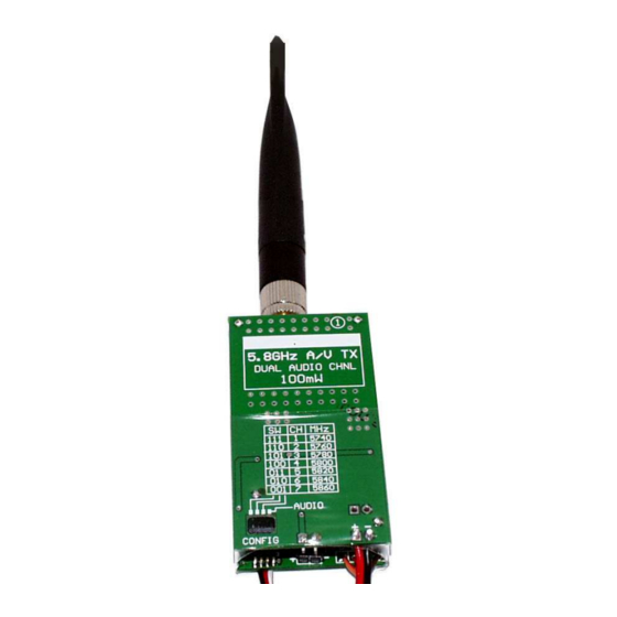
This 5.8Ghz 100mW A/V transmitter kit provides a custom printed circuit
board set and quality electronic components. All you need to add is an
antenna of your choice and about three hours of your time.
NOTICE: This kit involves precision SMD soldering and it is NOT intended for
beginners to assemble. It is suitable for amateur radio hobbyists and RF
technicians. The builder must have good quality soldering tools, an anti-static
work environment, and electronic assembly experience.
Note: This transmitter will require a ham radio license for hobby applications. Some
countries may prohibit use. Please consult your government's spectrum regulations
before using this device.
QTY
DESCRIPTION
====
===================
3
.1uF Cap
4
47uF 6V Cap
1
47uF 16V Cap
3
330uF Cap
3
3.3K Resistor
1
22uH Inductor
1
DL4001 Diode
2
KF50BDT
1
DIP Switch
1
SMA-RP Connector
1
Tall Post Header, 4-pin
20"
2-Cond Zip Wire
10"
3-Conductor Wire
1.75"
Heatshrink, 2" Size
1
Double-sided foam pad N/A
1
AWM681TX Module
1
Printed Circuit Board Set
The following accessories are available separately. You may use our recommendations or any
suitable equivalent:
AVAILABLE ACCESSORIES
5.8GHz 8dBi Patch Antenna, #HG5808P-SMA and Coax Cable #CSR400 or #CSR316.
5.8GHz 5dBi Patch Antenna, #AWM5.8ANT
5.8GHz 4dBi Dipole Antenna, #ANTDRP-5.8.
5.8GHz 2dBi Dipole Antenna, #ANTTRP-5.8.
Tiny-Mic Amplified Microphone, #MIC-001
AV681TX-Kit, Rev B
AV681TX 5.8GHZ A/V TRANSMITTER KIT
Rev-B Hardware
INTRODUCTION
B
M
ILL OF
ATERIALS
DESIGNATOR
============
C1, C3, C8
C6, C7, C20, C22
C21
C2, C4, C5
R1, R2, R3
L1
D20
U20, U21
S1
N/A
PCB Assy
DC-IN
AV-IN
N/A
#AWM681TX
PCB
Page 1
NOTES
=========================
0805 pkg.
Observe polarity. 3528-21pkg.
Observe polarity. 6032-28 pkg.
Observe polarity. 7343-31 pkg.
0805 pkg.
3225 pkg.
Observe polarity. MELF pkg.
TO-252 pkg.
SOIC Package
Antenna connector
Cut into one 2-pin and two 1-pin
Red/Black, 26AWG
Brown/Red/Orange, 32AWG
See text
See text
Static sensitive, handle with care.
2-piece set
© Nov-03-2008
Advertisement
Table of Contents

Related Manuals for DPCAV AV681TX

Summary of Contents for DPCAV AV681TX
- Page 1 AV681TX 5.8GHZ A/V TRANSMITTER KIT Rev-B Hardware INTRODUCTION This 5.8Ghz 100mW A/V transmitter kit provides a custom printed circuit board set and quality electronic components. All you need to add is an antenna of your choice and about three hours of your time.
- Page 2 Install C6 and C7 (47uF/6V caps). Install C2, C4, and C5 (330uF caps). Install L1 (inductor). Install S1 (4-position switch). Orient it so that the “1234" text is at the front edge. ä Figure 3, Side AV681TX-Kit, Rev B Page 2 © Nov-03-2008...
- Page 3 Correct all problems before proceeding. Temporarily apply power (6.5VDC to 8.5VDC) to the DC-IN cable. Using a digital voltmeter, verify 5.0VDC (±0.15V) at the P1 pads and the CAM-PWR cable. AV681TX-Kit, Rev B Page 3 © Nov-03-2008...
- Page 4 RF module’s top tin lid to the tin metal base. This will help prevent video noise. AV681TX-Kit, Rev B Page 4 © Nov-03-2008...
- Page 5 Note: The MIC input feature uses the right audio channel. Do not use the right channel on the A/V-IN input if a Microphone is installed on the MIC input. Figure 8, A/V Cables AV681TX-Kit, Rev B Page 5 © Nov-03-2008...
- Page 6 The three switches are set as follows: 5740 OFF = switch open (Front position) 5760 5780 = switch closed (Back position) 5800 5820 5840 5860 AV681TX-Kit, Rev B Page 6 © Nov-03-2008...
- Page 7 OFF (SW-4 open). TECHNICAL INFORMATION For complete technical information, please consult the AWM681TX data sheet (available from dpcav.com’s web site) and the attached schematic. NOTICE Digital Products Company, or their distributors, have no control over the assembly and use of this A/V RF system.
Need help?
Do you have a question about the AV681TX and is the answer not in the manual?
Questions and answers