
Related Manuals for uniwatt UTE202NP Series

Summary of Contents for uniwatt UTE202NP Series
- Page 1 UTE202NP SERIES NON PROGRAMMABLE ELECTRONIC THERMOSTAT Energy Verified INSUTE202NP1215 UNIWATT is a line of products manufactured by Stelpro. For more information please contact customer service.
- Page 2 WARNING Before installing and operating this product, the owner and/or installer must read, understand and follow these instructions and keep them handy for future reference. If these instructions are not followed, the warranty will be considered null and void and the manufacturer deems no further responsibility for this product.
-
Page 3: Parts Supplied
DESCRIPTION The UTE202NP electronic thermostat can be used to control electric heating units such as electric baseboards, convectors, or forced-air units. It keeps the temperature of a room at the requested set point with a high degree of accuracy. This product is designed for installations with electrical current - with a resistive load - ranging from 1.25 A to 8.3 A (120/240 VAC). -
Page 4: Installation
INSTALLATION SELECTION OF THE THERMOSTAT LOCATION The thermostat must be mounted to a connection box on a wall facing the heating unit, at around 1.5 m (5 feet) above the floor level, on a section of the wall exempt from pipes or air ducts. Do not install the thermostat in a location where temperature measurements could be altered. -
Page 5: Wire Installation
3. Make the electrical connections using the supplied solderless connectors. When making the connection with aluminum wire, make sure that you are using connectors identified CO/ALR. Please note that the thermostat wires do not have polarity. Therefore, the way they are connected is not important. 2-WIRE INSTALLATION 4-WIRE INSTALLATION INSUTE202NP1215... - Page 6 4. Open the door with your hand or by using a flat screw driver. a. With hand: open by freeing the door at the top right corner of the thermostat. b. Using a flat screw driver: insert the screw driver in the side slot at the top right corner of the thermostat and turn delicately until the door is freed.
-
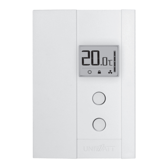
Page 7: Operation
OPERATION Ambient temperature/ Set point Heating power indicator Pictograms Fan mode Frost-free warning Comfort mode Security mode Top button Bottom button TEMPERATURE SET POINTS The figures displayed above the pictogram indicate the temperature set point. It can be displayed in degrees Celsius or Fahrenheit (see “Display in degrees Celsius/ Fahrenheit”). - Page 8 DISPLAY IN EITHER DEGREES CELSIUS/FAHRENHEIT The thermostat can display the ambient temperature and the set point in degrees Celsius (standard factory setting) or Fahrenheit. 1. To switch from degrees Celsius to degrees Fahrenheit and vice versa, simultaneously press down the two buttons for 3 seconds. Once the three seconds are over the °C or °F symbol will flash.
-
Page 9: Security Mode
SECURITY MODE It is possible to impose a maximum temperature set point by activating this mode. Then, it becomes impossible to exceed this set point, regardless of the current mode (Day/Night). However, it is still possible to lower the set point at your discretion. - Page 10 When the Fan mode is activated, the stop or minimum heating time (off/on) for a complete 10 minute cycle is established at 90 seconds (factory setting). You can adjust it from 90 to 300 seconds. This is done to limit the amount of times the thermostat will turn on or off.
-
Page 11: Troubleshooting
TROUBLESHOOTING PROBLEM DEFECTIVE PART OR PART TO CHECK • In normal operating conditions, the thermostat hous- ing can reach nearly 40°C at maximum load. That is The thermostat is hot. normal and will not affect the effective operation of the thermostat. -
Page 12: Limited Warranty
LIMITED WARRANTY TECHNICAL SPECIFICATIONS This unit has a 2-year warranty. If SUPPLY VOLTAGE: 120/208/240 VAC, 50/60 Hz at any time during this period the unit becomes defective, it must be MINIMUM ELECTRICAL CURRENT WITH A RESISTIVE LOAD: returned to its place of purchase 1.25 A with the invoice copy, or simply 150 W @ 120 V...
Need help?
Do you have a question about the UTE202NP Series and is the answer not in the manual?
Questions and answers