
Related Manuals for Diablo Controls DSP-15

Summary of Contents for Diablo Controls DSP-15
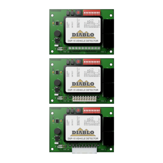
- Page 1 User Manual DSP-15 Vehicle Detector DSP-15-T Terminal Block DSP-15-M Male Molex DSP-15-F Female Molex Pros Who Know Trust Diablo DSP15_MAN_C 11/27/18 Page 1 of 23...
-
Page 2: Table Of Contents
Power LED Shows Two Quick Flashes Once Every Two Seconds................21 Detect LED Intermittently Comes On / Stays On Without a Vehicle Present ............22 Detect LED Will Not Come On With a Vehicle Present ..................23 DSP-15 User Manual Page 2 of 23 DSP15_MAN_C... -
Page 3: Figures
Figure 4: Outputs with Extension ..........................11 Figure 5: Outputs with Delay and Extension ......................11 Figure 6: Power LED States ............................14 Figure 7: Detect LED States ............................. 15 Figure 8: Loop Installation ............................18 DSP-15 User Manual Page 3 of 23 DSP15_MAN_C... -
Page 4: Introduction
2. Introduction The DSP-15 Detector is intended to be a top of the line single channel detector. Many features have been included which are normally found only on more expensive models. The small package is powered by a high- performance 8-bit microcontroller that does not skimp on performance. The DSP-15 Detector was designed to retrofit into existing locations that may require a detector upgrade. -
Page 5: Electrical Data
10.5 volts to 30 volts AC or DC 75 milliamps maximum. Environmental Data Operating Temperature: -35°F to 165°F (-37°C to 74°C) Storage Temperature: -40°F to 176°F (-40°C to 80°C) Humidity: Up to 95% relative humidity non-condensing DSP-15 User Manual Page 5 of 23 DSP15_MAN_C... -
Page 6: Mechanical Data
Housing Material: Bare PC Board Housing Size: .768 inches (High) x 2.90 inches (Wide) x 4.125 inches (Deep) 19.51 mm (High) x 73.66 mm (Wide) x 104.77 mm (Deep) Figure 1: Physical Dimensions DSP-15 User Manual Page 6 of 23 DSP15_MAN_C... -
Page 7: Features And Functions
The output will not pulse again until the loop has been reoccupied and any enabled delay has timed out. DSP-15 User Manual Page 7 of 23... -
Page 8: Fail-Safe Vs Fail-Secure
The B output is always fail-secure when not in the fail output mode. The DSP-15 is one of the few vehicle detectors that honors fail-safe and fail-secure even in the absence of power. Inside the unit, on the main PC board, are three jumpers that set the failure mode. When placed in the fail-safe position, the A output relay will be fail-safe in the absence of adequate voltage. -
Page 9: Frequency (Dip Switches 1 And 2)
For those instances where a longer period is desired, extended presence will hold that same vehicle for about 19 or 20 hours. This is quite a long time, but it isn’t infinite. The DSP-15 does not have infinite presence. -
Page 10: Output B Selection (Dip Switches 5 And 6)
Pulse on Exit: Every time the loop becomes vacant or a vehicle is tuned out, a single 250 milliseconds pulse will be output on the B output. Fail: If the DSP-15 recognizes some type of loop failure, a continuous output on the B output will be given. The B output will remain activated until the failure is corrected. -
Page 11: Figure 3: Outputs With Delay
Figure 3: Outputs with Delay Figure 4: Outputs with Extension Figure 5: Outputs with Delay and Extension DSP-15 User Manual Page 11 of 23 DSP15_MAN_C... -
Page 12: Sensitivity Boost (Dip Switch 7)
This interval is indicated by the red Detect LED blinking slowly at 200 milliseconds on followed by 200 milliseconds off repeatedly until the interval is complete. The delay interval is fixed at 2 seconds. DSP-15 User Manual Page 12 of 23 DSP15_MAN_C... -
Page 13: Indicators
Indicators The DSP-15 is equipped with two LED indicators: Power (Green) and Detect (Red). Power LED – The green power LED indicates these possible states: The voltage applied to the detector is less than the minimum display voltage of approximately 7.75 volts. The LED will be off. -
Page 14: Figure 6: Power Led States
LED will turn off for 500 milliseconds, on for 500 milliseconds, blink repeatedly with 50 milliseconds on followed by 50 milliseconds off for one second, and then display its normal state. DSP-15 User Manual Page 14 of 23 DSP15_MAN_C... -
Page 15: Figure 7: Detect Led States
Note: There is no delay interval for any newly arriving vehicle if a vehicle is already in the detection area or the detector is in the extension interval. Figure 7: Detect LED States DSP-15 User Manual Page 15 of 23 DSP15_MAN_C... -
Page 16: Installation
The gauge of the wire can be 20 AWG as long as the detector is within 50 feet of the loop in cable distance. For 50 to 100 feet, use at least 18 AWG wire. At greater than 100 feet, use a 16 AWG DSP-15 User Manual Page 16 of 23... - Page 17 More is better. Going too deep with the saw cut is also a concern. Deep cuts in a road surface may impact the structural strength of the roadway, especially if any reinforcement material is cut. Using a smaller gauge of wire will allow for shallower saw cuts. DSP-15 User Manual Page 17 of 23 DSP15_MAN_C...
-
Page 18: Figure 8: Loop Installation
However, these are not hard guidelines and specific circumstances will determine which type of sealant should be used. DSP-15 User Manual Page 18 of 23 DSP15_MAN_C... - Page 19 Once the loop wire leaves the saw slot it should be twisted at least three times per foot. More is better. The twists should be kept tight to be most effective in reducing the effects of electrical interference. DSP-15 User Manual Page 19 of 23...
-
Page 20: Troubleshooting
Swap the loops between a working detector and a failing detector. If the problem follows the loop the loop is the problem. If it stays in the same detector, replace the detector. DSP-15 User Manual Page 20 of 23 DSP15_MAN_C... -
Page 21: Power Led Flashes Quickly (5 Hz)
Another is that the loop wire has been damaged where it enters or exits a conduit or junction box, or that a conduit that the loop wire is in has been damaged (crushed, kinked, bent, cut, etc.). DSP-15 User Manual Page 21 of 23 DSP15_MAN_C... -
Page 22: Detect Led Intermittently Comes On / Stays On Without A Vehicle Present
Another possibility is metal objects in close proximity to the loop. Utility manhole covers are objects that may move slightly when vehicle tires drive over them, especially if the vehicle turns while a tire in on the cover. Most DSP-15 User Manual Page 22 of 23... -
Page 23: Detect Led Will Not Come On With A Vehicle Present
If the problem follows the loop the loop is the problem. If it stays in the same detector, replace the detector. DSP-15 User Manual Page 23 of 23...
Need help?
Do you have a question about the DSP-15 and is the answer not in the manual?
Questions and answers