Table of Contents
Advertisement
INSTALLATION OPERATION and MAINTENANCE MANUAL
High Efficiency Packaged Models DC Series B, Air Conditioning
Safety Labeling and Signal Words...........2
General Description ..................................3
Unpacking, Inspection ........................3
Design Certification..............................3
Codes & Ordinances ............................3
Installation..............................................3- 6
Unit Location, Clearances ...................3
Curb Installation ...................................3
Rigging...................................................4
Electrical ................................................4
Ductwork ...............................................5
Condensate Piping ...............................5
Gas Piping and Venting ...................5- 6
Cooling System Options .......................6- 8
Hot Gas Bypass ....................................6
Head Pressure Control.........................6
Variable Speed Control ........................6
Hot Water Heat Recovery.................7, 8
Mechanical Adjustments ....................9, 10
Evaporator Blower Fan ..................9, 10
Electrical System Options ......................10
Air Flow Switch...................................10
!
WARNING: READ SAFE OPERATION RULES AND MANUAL CAREFULLY
1
Systems, Model Sizes 036 Thru 420
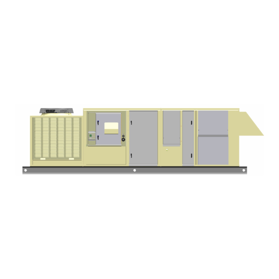
No Heat Recovery Cabinet
Extended Heat Recovery Cabinet
TABLE OF CONTENTS
Clogged Filter Indicator ..........................10
Convenience Outlet ............................10
Exhaust Fan Interlock ........................10
Power Through the Curb ...................10
Firestat.................................................10
TM
Sure-Trip
..........................................10
DDC controls.......................................10
Sequence of Operation ...........................11
Heating, Steam/Hydronic ...................11
Gas Heat ..............................................11
Electric Heat ........................................11
Energy Conservation Wheel..............12
Trouble Shooting Guides...................13-18
General Refrigeration Circuit .......13-16
Varispeed™ Condenser Control .......15
Hot Gas Bypass Regulator ................16
Gas Furnace ........................................17
R410A
Advertisement
Table of Contents


Need help?
Do you have a question about the DC Series and is the answer not in the manual?
Questions and answers
What is the approximate weight of a DC 360 unit?