Table of Contents
Advertisement
Quick Links
Advertisement
Table of Contents

Subscribe to Our Youtube Channel
Summary of Contents for Matco Tools MAXIMUS MDMAXTI
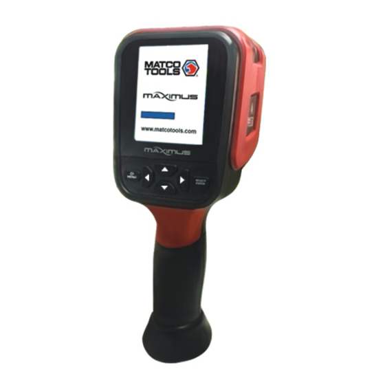
- Page 1 Thermal Imaging Camera Instruction Manual...
-
Page 2: Table Of Contents
Contents 1. Overview 10. Introduction to “Setting” Sub-menu 2. Considerations and Safety Maintenance 10.1 Time Setting 3.Image Reading 10.2. Enable/disable of the highest and lowest temperature cursor 4. Performance index 11. “Data base” submenu 5. Product Description 11.1 Database description 5.1. -
Page 3: Overview
2. Considerations and Safety Maintenance 1. Overview Please read the instruction for use carefully in order to ensure correct This product is an infrared camera that integrates surface temperature measurement result: measurement and real-time thermal image. The traditional inferred thermometer needs to measure every component one by one while it is not Don’t use the device in explosive, flammable or corrosive environment. -
Page 4: Performance Index
4. Performance index 5. Product Description Display screen TFT display screen 5.1. Instruction to structure Screen size 3.2 inches Display Pixels 320x240 Infrared image resolution 220x160 visible image resolution 300,000 Field angle/shortest focus length 35°x26°/0.15m Thermal sensitivity 0.07℃ Temperature measurement range -20℃... - Page 5 Please open the cap in use Visible light camera Micro USB Please open the cap in use Infrared imaging sensor Image capture key Battery...
-
Page 6: Key Description
5.2. Key Description 5.3. Key Description Current emissivity Central point temperature Battery power SELECT The lowest ENTER MENU temperature cursor Color code Temperature cursor at The highest central point temperature On/off/menu key Navigation key: Up, Selection key/ cursor down, left and right entry key Maximum value/ minimum value of... -
Page 7: Introduction To "Image" Sub-Menu
7. Introduction to “image” sub-menu Image capture: press the image capture key. When the capture is successful, the screen will display “save photo?” prompt. Select "Yes" or 7.1. View image "No" to delete the image, press the " " " "... -
Page 8: Introduction To "Color Palette" Sub-Menu
8. Introduction to “color palette” sub-menu 8.2 Application of color palette 8.1 Color Palette Description The menu of color palette can change the false color of infrared thermal Color palette image. The product provides five types of color palette: rainbow, iron oxide Spectra red, cold color, white heat and black heat. -
Page 9: Introduction To "Emissivity" Sub-Menu
9. Introduction to “emissivity” sub-menu 9.2. Emissivity setting 9.1 Emissivity Description The product is provided with four types of object measurement modes: Coarse object (0.95) The emissivity of the product can be adjusted from 0.01 to 1.00 with the Semi-matte object (0.85) default value of 0.95. -
Page 10: The Emissivity Value Of Common Materials
10. Introduction to “Setting” Sub-menu If you select “Custom” emissivity, press “SELECT/ENTER” to enterTo edit the status, press “ ” / “ ” to select the number to be modified, press Press “ /MENU” key to select the “ ”(setting) option in the main “... -
Page 11: Time Setting
10.1. Time setting 10.2. Enable/disable of the highest and lowest temperature cursor As shown in the figure, after selecting “ ” (set time), press “ ” in the navigation key to enter the setting time. As shown in the figure, after selecting “ ”... -
Page 12: Data Base" Submenu
11.“Data base” submenu After entering the “Data base” menu, press “ “ to enter the “Powertrain & Exhaust”menu, then press “ “ to view the “Misfire” submenu. As 11.1. Database description shown below: Through the image map stored in the database, the customer can compare whether the captured thermographic image is normal. -
Page 13: Database Upgrade
After entering the “Coil” submenu, press “SELECT/ENTER” to enter the 2. Open the USB flash drive and copy the upgrade package with the image view, press “ ” and “ ” to view the three images of pak suffix to the root directory of the USB flash drive. Known Good, Known Bad and Tip. -
Page 14: Image Overlapping" Submenu
12.“Image overlapping” submenu 12.1. Description of image overlapping Image overlapping makes it easier for users to understand the infrared images by using aligned visible images and infrared images. The use of image overlapping can capture the visible image of every infrared image so as to display the temperature distribution in the target region correctly and share with other people more effectively.
Need help?
Do you have a question about the MAXIMUS MDMAXTI and is the answer not in the manual?
Questions and answers