
Summary of Contents for IBS DBS
- Page 1 IBS Intelligent Battery System GmbH Seestrasse 24, CH-3600 Thun, Schweiz Tel: +41 33 221 06 16 E-Mail: info@ibs-tech.ch IBS-DBS Dual Battery System Manual IBS-DBS_en_v1.2.2.doc...
-
Page 2: Table Of Contents
Installation / Wiring ..........................10 Classic 12V Installation ........................10 Classic 12V with RBM ........................11 DBM Supported Installation ......................12 Additional functions / applications with IBS-DBS ................12 Note ............................13 Triple battery installation (with DBR) ....................14 Classic 24V Installation ........................15 Classic 24V with RBM ........................ -
Page 3: Language / Sprache / Langue / Lingua
Für Handbücher in einer anderen Sprache, Links folgen oder QR-Code scannen. Pour les manuels dans une autre langue suivez le link ou scannez le code QR. Per il manuale in una otra lingua seguite il link o scannerizzate il codice QR. English Deutsch Francais Italiano Uscita prossimamente http://www.ibs-tech.ch/download/manuals-ibs.html... -
Page 4: Product Description
Product description The classic IBS-DBS Dual Battery System is used for charge distribution while driving (alternator charging) and disconnecting the batteries after driving (alternator off). For emergencies, the batteries can be manually connected for 30 minutes or 2 hours. For example, in the case of an empty / faulty starter battery (Main) the motor can be started from the additional battery Aux (RBM necessary). -
Page 5: Applications
Applications... -
Page 6: Combinations Of Ibs Devices
Combinations of IBS devices... -
Page 7: Mounting
(Not on the relay connections). After installation Carry out the control steps (you can find the document on our website at www.ibs-tech.ch \ Downloads \ Testprocedures IBS- DBS_Test_e1.pdf or the QR code next to it). -
Page 8: Starting The Monitor
*Select the desired mode 1-6 or S and follow the instructions in Setting the mode. **The monitor may have already been set in advance. To find out which mode the DBS is in, follow the instructions in the software display on page 9. -
Page 9: Software Display
Software Display As soon as you insert the monitor and it is connected to the starter battery, it will display the software version and the currently set mode for a few seconds as following: Software version The actual software version is indicated by the display bars Main and Aux. Number of luminous Led's of the Main-Bar, equals the first number and the number of Led's of the Aux-Bar give the second number of the actual device software version. -
Page 10: Installation / Wiring
Installation / Wiring Classic 12V Installation Please read the installation steps before performing for a better understanding. If possible, install the wire in a protective tube and fasten with wire ties. Do not attach to hot engine parts: Risk of fire! 1. -
Page 11: Classic 12V With Rbm
Classic 12V with RBM Please read the installation steps before performing for a better understanding. If possible, install the wire in a protective tube and fasten with wire ties. Do not attach to hot engine parts: Risk of fire! 1. Route the wires from the wire set from the driver's cab into the engine compartment. 2. -
Page 12: Dbm Supported Installation
DBM Supported Installation Additional functions / applications with IBS-DBS It is necessary to have a micro controlled version of the IBS-DBS to access all the extra functions. µC- There has to be the light blue sign on the cover of the IBS-DBS. -
Page 13: Note
DBM20A manual). (Do not continue installation until standby mode is activated). 7. Now connect the green line of the IBS-DBS to the yellow Link / Prog line of the DBM20A. 8. Finally connect the blue (+ Aux) line. -
Page 14: Triple Battery Installation (With Dbr)
8. Connect the IBS-DBR to the power wire: From battery bord (Aux) plus to terminal 87. From plug or trailer / box battery terminal to terminal 30. From terminal 85 to minus. 9. Connect IBS-DBR button to terminal 86 and minus. -
Page 15: Classic 24V Installation
Classic 24V Installation Please read the installation steps before performing for a better understanding. If possible, install the wire in a protective tube and fasten with wire ties. Do not attach to hot engine parts: Risk of fire! 1. Route the wires from the wire set from the driver's cab into the engine compartment. Crimp the wire lugs. -
Page 16: Classic 24V With Rbm
Classic 24V with RBM Please read the installation steps before performing for a better understanding. If possible, install the wire in a protective tube and fasten with wire ties. Do not attach to hot engine parts: Risk of fire! 1. Route the wires from the wire set from the driver's cab into the engine compartment. 2. -
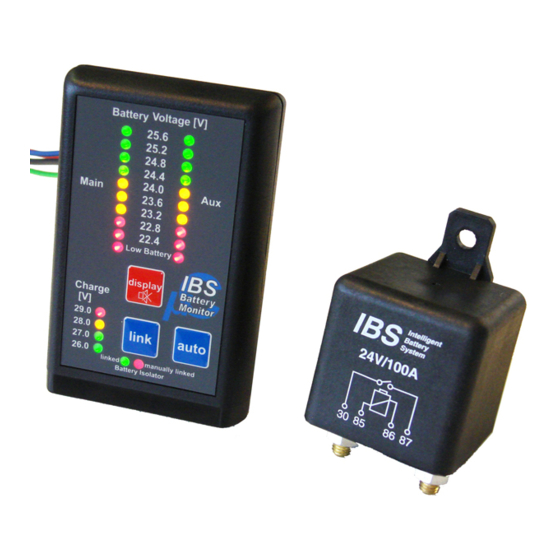
Page 17: Explanation: Display
Explanation: Display Battery Voltage & Charge The voltages of the connected batteries can be read on the respective LED bar. As soon as charge is present on a battery, this is indicated by the charge LED. Linked LED The linked LED indicates whether the batteries are linked via the relay or not. -
Page 18: Explanation: Buttons
Explanation: Buttons Display button By briefly pushing the display button, the display is activated (which automatically turns off after 30 seconds). Push and hold the display button for approx. 2 seconds, the display can be dimmed (back to full ... -
Page 19: Error Description
Error description List of errors The DBS Monitor shows errors as follows Error Illustration Description No flashing lights, no acoustic signal No error Low Battery Led flashing, acoustic Deep discharge Charge and check the batteries, signal possibly defective battery Link error Linked Led flashing, audible signal Possible faulty battery or defective relay. -
Page 20: Specifications
Tighten torque relay M6 bolts 8 Nm max Dimensions packaging 80 x 92 x 215 mm Weight packaged 0.75 kg Guarantee 5 Jahre Nach CISPER 25 (Automotive) Homologation E24 ECE 10R Production standard ISO9001:2008 Click on installation system IBS RMS System... -
Page 21: Accessories
Accessories IBS Partnumber Designation IBS-RBM 12V/24V RBM Relay Booster Modul 12V or 24V IBS-DBR 12V/24V DBR Dual Battery Relay 12V or 24V DBM20A Dual Battery Management 20A IBS-DBM20A... -
Page 22: Notes
Notes... -
Page 23: Delivery Content
Delivery content IBS-DBS Monitor IBS-Relay IBS-RMS Mounting bracket Terminal kit Wire kit Manual ... - Page 24 IBS-DBS Manual from 15.08.2017 Manual Version 1.2.2 Software Version 8.1 IBS – Intelligent Battery System GmbH Seestrasse 24 3600 Thun / Switzerland Phone: +41 (0)33 221 06 16 Hotline: +41 (0)33 221 06 18 www.ibs-tech.ch info@ibs-tech.ch MADE IN SWITZERLAND...
Need help?
Do you have a question about the DBS and is the answer not in the manual?
Questions and answers