
Related Manuals for aeolus UC-1901M


Summary of Contents for aeolus UC-1901M
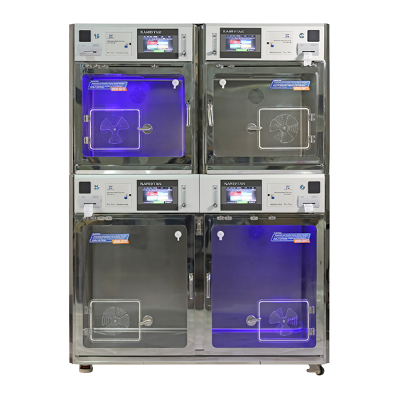
- Page 1 Professional Multifunctional Veterinary Intensive Care Unit Professional Vet Equipments Supplier UC-1901 UC-1801 WMS-1501 -10F Distributor Contacts User Manual...
-
Page 2: Table Of Contents
Overview CONTENTS Overview …………………………………………......Product dimensions ……………………………………………..Side View General usage guidelines ………………………………….……..General opreation tips ………………………………......Radio requency interferece ………………………………....Choosing the working space for the unit ........Parameters ……………………………………………...... Operation guidance ……………………………………………..Setting interface ……………………………………………....Top View Setting mode ……………………………………………....Trouble shooting ………………………………………….... -
Page 3: Product Dimensions
Product Dimensions General Usage Guidelines The KaniStar UC-1901 Multifunctional Veterinary Intensive Care Unit is For Animal Use Only. 696mm ( 2 � 3 13/32 inch) There is no reference in this handbook for human hospitals or home users. 850mm ( 2 � 9 15/32 inch) Normothermia maintenance, fluid transfusion, oxygen supplement, blue light therapy, nebulization treatment, emergency rescue, in house observation can all be carried out by this unit. -
Page 4: Choosing The Working Space For The Unit
Care should be taken when choosing the working space for this unit. Professional Veterinary Product Name Control Panel 8.4”, 171mmW×128mmH Intensive Care Unit Model Number UC-1901M/L/BK Screen Type Resistive The unit should be used indoors only, in a cool 1509mmW×884mmD×1899mmH Max. Power dry room with stable temperature and humidi- Dimension 1.3KW... -
Page 5: Operation Guidance
Operation Guidance Setting Interface On this interface, you will find the following functions and displays. Main Interface Navigation 1. Setting Mode Allows the operator to switch on/off and set all the changeable running parameters for most functions. Operating Status – Indicating the varied functions running in real time. -
Page 6: Setting Mode
25.0 30.0 Density 3. Oxygen Density Setting Setting Mode 1500 Density a) Enter “Setting Mode”. b) Click the existing oxygen figure in “O Density” bar. c) Input the desired oxygen density value by clicking the newly 21~65 中 opened setting box, within the range of 21 -65%. Auto d) Click “Enter”... - Page 7 25.0 1500 30.0 11. Negative Ion Set 8. Emergency Vent Setting 1500 Nega�ve Ion Timer a) Enter “Setting Mode”. MIDDLE 中 The emergency ventilation port is designed as a fail-safe, for Emergency Vent Se�ng b) Click the existing time figure in “Negative Ion Timer” bar. Nega�ve Ion Timer necessary fresh air in critical situations like a power supply 中...
- Page 8 25.0 30.0 No other function can be set when the unit is being disinfected. The disinfecting process can be Density Setting Zero and Full. cancelled at any time returning the unit to its previous settings. All other lights will be cancelled and all Note: You need a pass code to enter this page, please contact your local supplier or service center 1500 functions will be stopped during the disinfection process.
-
Page 9: Troubleshooting
22. Large Compartment Divider Application Alarming Components With this very unique and practical feature, the large compartment can be divided into two separately controlled medium compartments. By loosening the two latches on top of the front 1. Temperature Sensor & Humidity Sensor Replacement column in the middle of the large compartment, it can be pulled out at the top then up to remove, then the Both Temperature and humidity sensors can be found can be found at the innermost top corner of the... -
Page 10: Non-Alarming Components
4. CO Sensor 2. Lighting Systems 3. Negative Ion Generator Open the grid at the top corner nearest to the Open and remove the top cover on ICU door hinge. compartment to expose internal components. If CO sensor alarm sounds, Locate faulty light component and replace it Please find the negative ion generator, check if please check the emergen-...
Need help?
Do you have a question about the UC-1901M and is the answer not in the manual?
Questions and answers