
Related Manuals for Weidmüller maxGUARD

Summary of Contents for Weidmüller maxGUARD
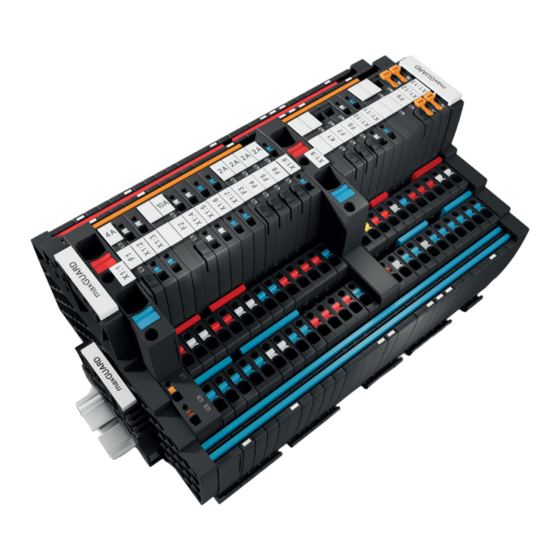
- Page 1 Load monitoring with integrated potential distribution maxGUARD Manual Letʼs connect.
-
Page 2: Table Of Contents
10.1 Required tools Product overview 10.2 Disassembling a module General technical data 10.3 Disassembling a maxGUARD station Tripping characteristics 10.4 Disposing of a maxGUARD station Conformity and approvals LED indicators and troubleshooting Configuration ANNEX Configuration in the Weidmüller Configurator Normal tripping characteristic 1A... -
Page 3: About This Documentation
Complete documentation Risk of injury! Observe the documentation delivered with the Notes with the signal word “Caution” warn maxGUARD products. you of situations that may result in injury if you do not follow the instructions given in this manual. All documents are available to download from the Weidmüller website. -
Page 4: Safety
FIM-0..., AMG FIM-C...). The potential distributors of the according to IEC 61340-5-1 and IEC 61340-5-2 must be maxGUARD family can be used for contact replication of the observed. The packing and unpacking as well as the assem- load monitor output. Only Weidmüller ZQV 4N cross-connec- bly and disassembly of a device may only be carried out by tors may be used for connections within a station. -
Page 5: Use In Explosive Risk Zones
2 Safety | Use in explosive risk zones Use in explosive risk zones A list of all maxGUARD products that may be used in explo- sive atmospheres, zone 2, can be found in section 3.9. If maxGUARD products are used in explosive risk zones, the fol- lowing additional notes apply: –... -
Page 6: System Overview
End plate End bracket maxGUARD is a modular system for building customised All connections between the modules of a maxGUARD sta- 24 V control voltage distributors. It consists of electronic tion are established using cross-connectors. All connection load monitors, potential distribution terminals, and feed-in, terminals are PUSH IN connections, are colour-coded and control and alarm modules. -
Page 7: Mode Of Operation And Connection Concept
AMG CM AMG ELM AMG OD Left: Main strands and load outputs (red: +24 V, blue: 0 V) Right: Communication via the internal signal line (orange) All connections between the modules of a maxGUARD sta- A maxGUARD station has three main internal connection tion are established using cross-connectors. channels: The main connection channels are designed as double – +24V main strand for +24 V potential channels. -
Page 8: Functions
Surge detection Technical data Active feed-in modules, control and alarm modules as well as all load monitors are equipped with surge detection. If the input voltage of these modules exceeds 31.2 V, the module LED will quickly flash red. 2526740000/02/03.2018 Manual maxGUARD... -
Page 9: Markers
– Markers for printing with Weidmüller PrintJet ADVANCED – Order No. 1112950000, WAD 8, yellow, PA 66 (Order No. 1324380000) – Order No. 1818400000, WS 10/6, white, PA 66 – Markers for printing with Weidmüller THM MMP (Order No. 2430820000) – Order No. 2007160000, WS 8/6 MM, white, PC-ABS/ 2526740000/02/03.2018 Manual maxGUARD... -
Page 10: Internal Fuse
AMG ELM Q6666 4x (2x 6.3 A) – Order No. 1634780000, ESO 7 yellow, paper – Order No. 1670390000, ESO 7 P white, polyester AMG ELM Q2244 4x (2x 6.3 A) – Order No. 1670400000, ESO 7 P yellow, polyester AMG ELM Q2266 4x (2x 6.3 A) 2526740000/02/03.2018 Manual maxGUARD... -
Page 11: Product Overview
3 System overview | Product overview Product overview maxGUARD components – standard version The following maxGUARD products have uncoated PCBs and standard certification (see section 3.9). Product designation Function Order No. Feed-in modules, control module, alarm module AMG FIM-0 Feed-in module, passive 2081870000 AMG FIM-C Feed-in module, active (reset, alarm) - Page 12 3 System overview | Product overview maxGUARD components – enhanced version The following maxGUARD products have coated PCBs and enhanced certification (see section 3.9). Product designation Function Order No. Feed-in modules, control module, alarm module AMG FIM-0 EX Feed-in module, passive 2082530000 AMG FIM-C EX Feed-in module, active (reset, alarm)
- Page 13 ZQV 4N/6 RD 2460780000 7-pole ZQV 4N/7 1528020000 ZQV 4N/7 BL 1528180000 ZQV 4N/7 RD 2460770000 8-pole ZQV 4N/8 1528030000 ZQV 4N/8 BL 1528190000 ZQV 4N/8 RD 2460760000 9-pole ZQV 4N/9 1528070000 ZQV 4N/9 BL 1528220000 ZQV 4N/9 RD 2460750000 10-pole ZQV 4N/10 1528090000 ZQV 4N/10 BL 1528230000 ZQV 4N/10 RD 2460740000 50-pole ZQV 4N/50 1528130000 ZQV 4N/50 BL 1528240000 ZQV 4N/50 RD 2460730000 2526740000/02/03.2018 Manual maxGUARD...
-
Page 14: General Technical Data
3 System overview | General technical data General technical data General Total length of a maxGUARD station max. 300 mm (with 50-pole cross-connector), max. 900 mm (with extension) Dimensions Height: 125 mm Width: 6.1/12.2/18.3/24.4 mm Depth 96.5 mm Number of bus participants max. 25 (incl. control or active feed-in module) Cross-connectors (type) ZQV 4N, max. - Page 15 1) If wire-end ferrules with plastic collars are used, the connector must be stripped 2 mm further than the contact surface length of the wire-end ferrule used (min. 3 mm longer for twin wire-end ferrules). Observe the information on the wire-end ferrule’s data sheet. All product-specific technical data can be found in the corresponding product description in chapters 5 to 7. 2526740000/02/03.2018 Manual maxGUARD...
-
Page 16: Tripping Characteristics
3 System overview | Tripping characteristics Tripping characteristics Enlarged representations and numerical values for the individual characteristics can be found in the annex Tripping characteristics, normal: 1A – 4A Tripping characteristics, normal, Class 2: 1A – 4A Tripping characteristics, normal: 6A – 12A Tripping characteristics, lag: 1A – 4A 2526740000/02/03.2018 Manual maxGUARD... - Page 17 3 System overview | Tripping characteristics Tripping characteristics, lag: 6A – 12A 2526740000/02/03.2018 Manual maxGUARD...
- Page 18 2082000000 AMG ELM-12 EX 2082010000 AMG ELM-6D CO 2082440000 AMG ELM-10D CO 2082470000 AMG ELM-1F EX 2082040000 AMG ELM-2F EX 2082050000 AMG ELM-4F EX 2082060000 AMG ELM-6F EX 2082310000 AMG ELM-8F EX 2082320000 AMG ELM-10F EX 2082430000 2526740000/02/03.2018 Manual maxGUARD...
-
Page 19: Conformity And Approvals
3 System overview | Conformity and approvals Conformity and approvals The filled cells in the following tables show the scope of ap- provals for the individual maxGUARD products. Standard version Conformity and approvals Designation Order No. TÜV Süd Class 2 AMG FIM-0 2082530000... - Page 20 II 3G Ex ec IIB T4 Gc Standards: EN 60079-0:2012 + A11 2013, EN 60079-7:2015 IECEx Certificate number: IECEx ULD 17.0018X Markings: Ex ec IIB T4 Gc Standards: IEC 60079-0 (Ed. 6) and IEC 60079-7 (Ed. 5) 2526740000/02/03.2018 Manual maxGUARD...
-
Page 21: Configuration
2-pole output relay, as the Feed-in modules should be positioned at the beginning of functional isolation at the MINUS output will be rendered a maxGUARD station and at the point where a station is ex- ineffective. tended (see section 4.8). -
Page 22: Installation Position And Mounting Distances
To this end, 50-pole cross-connectors may be cut to the required length. For maxGUARD stations with a length of up to 60 mm, cross- connectors with a suitable number of poles may be used. -
Page 23: Earthed And Non-Earthed Control Voltage Distributors
For longer signal lines, 50-pole cross-connectors may For earthed control voltage distributors, the earth potential is be cut to the required length. For maxGUARD stations with a the reference point for all signals between the maxGUARD length of over 300 mm, see section 4.8. -
Page 24: Connection To The Control Unit
The connection to a control board (PLC, remote I/O system) the maxGUARD station and the control board. may be non-isolated or isolated (potential-free). In non-earthed systems, it is preferable to use load monitors with a two-pole output relay. -
Page 25: Segmentation Of Control Voltage Distributors
Weidmüller relay modules distributors and solid-state relays. Within a maxGUARD station, load groups can be combined to form individually controlled and monitored segments. A +24 V segment always consists of a control module and at least one electronic load monitor. -
Page 26: Extending Control Voltage Distributors
This feed-in module should be placed after passive feed-in modules, a maxGUARD station can be ex- 50 grid units or at the end of the maxGUARD station. tended to a length of 150 grid units (approx. 915 mm). Existing maxGUARD stations can be extended in the same way. -
Page 27: Example Configurations
4 Configuration | Example configurations Example configurations Example: One segment without connection to a control unit Example: maxGUARD station without connection to a control unit This example shows a control voltage distributor for four se- The passive feed-in module feeds in the supply voltage. The... -
Page 28: - 1X Amg Elm-4F
4 Configuration | Example configurations Example: One segment with connection to a control unit Example: maxGUARD station with connection to a control unit This example shows a control voltage distributor for six se- The active feed-in module feeds in the supply voltage and lectively fused load circuits with connection to a control unit. - Page 29 4 Configuration | Example configurations Example: Two segments with connection to a control unit Example: maxGUARD station with two segments and connection to a control unit This example shows a control voltage distributor with two The active feed-in module feeds in the supply voltage and segments for seven selectively fused load circuits with con- connects the first segment to the control unit.
-
Page 30: Feed-In Modules, Control Modules, Alarm Modules
GND feed-in connection (16 mm GND main strand connection (0 V) Marker The passive feed-in modules are used to connect the feed-in conductors from the power supply. They connect the power supply to the main strands of the maxGUARD station. 2526740000/02/03.2018 Manual maxGUARD... -
Page 31: Active Feed-In Modules Amg Fim-C
Feed-in modules are used to connect the feed-in conductors. (typical) They connect the power supply to the main strands of the Width 12.2 mm maxGUARD station. The AMG ELM electronic load moni- Digital inputs tors can be controlled and monitored using active feed-in Input resistance 10 kΩ... -
Page 32: Control Modules Amg Cm
Fault-free operation Digital inputs Red, flashing Supply voltage error Input resistance 10 kΩ Alarm tripped or LOW➝HIGH: 15 V internal fault Input voltage hysteresis HIGH➝LOW: 5 V Reset tripped or Yellow Digital outputs ON/OFF tripped Active transistor output 24 V/ 20 mA Short-circuit-proof 2526740000/02/03.2018 Manual maxGUARD... -
Page 33: Alarm Modules Amg Am
Alarm signals and overload advance warnings can be trans- mitted potential-free to control boards using alarm modules. Width 12.2 mm Relay outputs Contact type NO contact Colour Meaning Permissible contact load 30 V/100 mA Alarm tripped I > Yellow Overload advance warning (I > 90%) 2526740000/02/03.2018 Manual maxGUARD... -
Page 34: 6 Electronic Load Monitors | Amg Elm-X
Colour Meaning Green Fault-free operation Load monitor is switched off Red, flashing Load monitor tripped Red, flashing fast Internal error Orange (red and green) Overtemperature detected Red, green, alternating Reset button deactivated for 30 seconds 2526740000/02/03.2018 Manual maxGUARD... - Page 35 , 3A , 4A , 6A , 6A , 8A , 10A , 12A Characteristics (delayed) , 4A , 6A , 10A , 12A Bus decoupling, bus coupling Alarm (tripped, fault) Overload advance warning Reset ON/OFF Button function Reset ON/OFF 2526740000/02/03.2018 Manual maxGUARD...
-
Page 36: Amg Elm-Xf
The tripping current and the tripping characteristic are fixed. Colour Meaning Green Fault-free operation Load monitor switched off Red, flashing Load monitor tripped Red, flashing fast Internal error Red, green, alternating Reset button deactivated for 30 seconds 2526740000/02/03.2018 Manual maxGUARD... -
Page 37: Amg Elm-6F
10,000 µF 15,000 µF 20,000 µF Overtemperature protection Width 6.1 mm 12.2 mm Tripping behaviour Adjustable Tripping current I 1 A 2 A 4 A 6 A 8 A 10 A Characteristics (normal) Characteristics (delayed) Bus decoupling, bus coupling Alarm (tripped, fault) Overload advance warning (I>90%) Reset ON/OFF Button function Reset ON/OFF 2526740000/02/03.2018 Manual maxGUARD... -
Page 38: Amg Elm-Xf Cl2
National Electric Code (NEC). The tripping current and the tripping characteristic are fixed. Colour Meaning Green Fault-free operation Load monitor switched off Red, flashing Load monitor tripped Red, flashing fast Internal error Red, green, alternating Reset button deactivated for 30 seconds 2526740000/02/03.2018 Manual maxGUARD... -
Page 39: Amg Elm-1F Cl2
Voltage drop at I 200 mV OUT,rated Capacitive load 4 700 µF Overtemperature protection Width 6,1 mm Tripping behaviour Adjustable Tripping current I 1 A 2 A 4 A Characteristics (normal) Characteristics (delayed) Bus decoupling, bus coupling Alarm (tripped, fault) Overload advance warning (I>90%) Reset ON/OFF Button function Reset ON/OFF 2526740000/02/03.2018 Manual maxGUARD... -
Page 40: Amg Elm-Qxxxx
Colour Meaning Green Fault-free operation Load monitor switched off Red, flashing Load monitor tripped Red, flashing fast Internal error Orange (red and green) Overtemperature detected Red, green, alternating Reset button deactivated for 30 seconds 2526740000/02/03.2018 Manual maxGUARD... - Page 41 Adjustable Tripping current I 2 A 4 A 6 A 2 A, 4 A 2 A, 6 A Characteristics (normal) , 4A , 6A Characteristics (delayed) Bus decoupling, bus coupling Alarm (tripped, fault) Overload advance warning Reset ON/OFF Button function Reset Yes, per channel ON/OFF Yes, per channel 2526740000/02/03.2018 Manual maxGUARD...
-
Page 42: Amg Elm-Xd C0
Colour Meaning Green Fault-free operation Load monitor switched off Red, flashing Load monitor tripped Red, flashing fast Internal error Orange (red and green) Overtemperature detected Red, green, alternating Reset button deactivated for 30 seconds 2526740000/02/03.2018 Manual maxGUARD... - Page 43 , 3A , 4A , 6A , 6A , 8A , 10A Bus decoupling, bus coupling Alarm (tripped, fault) Overload advance warning Reset ON/OFF Button function Reset ON/OFF Relay outputs Contact type NO contact Galvanic isolation All poles, functional 2526740000/02/03.2018 Manual maxGUARD...
-
Page 44: Potential Distribution Terminals
AMG ELM load monitors. The poten- load monitor via a cross-connector.. tial is fed in exclusively from the outputs of the load monitor via cross-connectors. AMG PD... block diagram AMG OD... block diagram 2526740000/02/03.2018 Manual maxGUARD... -
Page 45: Amg Md
MINUS output of the is fed in exclusively from the GND main strand via an internal load monitor via a cross-connector. connection. AMG MD... block diagram AMG XMD... block diagram 2526740000/02/03.2018 Manual maxGUARD... -
Page 46: Amg Dis
AMG ELM load monitors. The poten- tial is fed in exclusively from the outputs of the load monitor via cross-connectors. The disconnecting levers can be used for testing purposes to electrically isolate the connections to the outputs of the load monitors. 2526740000/02/03.2018 Manual maxGUARD... -
Page 47: Installation And Wiring
8 Installation and wiring | Preparations for installation Installation and wiring terminal rail must be fitted before the maxGUARD station is WARNING installed. Explosion risk! During installation work, sparks can form and The terminal rail must be attached to the substrate at inter- surfaces may become excessively hot. -
Page 48: Installing The Maxguard Station
8 Installation and wiring | Installing the maxGUARD station Installing the maxGUARD station Installation position and mounting distances A maxGUARD station can be operated in any installation position without derating. The mounting distance must be at WARNING least 20 mm on all sides. The minimum permissible conduc- Explosion risk! tor bending radii must be observed. - Page 49 Installing an end bracket ▶ Place the WEW 35/2 end bracket on the terminal rail and Installing an end bracket with an end plate (left) screw down tightly (3.5 mm screwdriver).
-
Page 50: Attaching Markers
If the total current is over 20 A, all main strands must each be equipped with two cross-connectors. Once the maxGUARD station has been mechanically in- stalled, the cross-connectors can be fitted in accordance with the installation drawing or wiring diagram. -
Page 51: Wiring
(panel etc.) has been disconnected from the power supply! The use of different-coloured cross-connectors simplifies as- sembly and enhances the clarity of the maxGUARD station. ATTENTION ▶ Cut the 50-pole cross-connectors to the required length Risk of destruction if polarity is incorrect! ▶... -
Page 52: Insulation Tests
– ▶ Connect all wires in accordance with the wiring diagram. 1.50 mm² 0635100000 0635100000 – All wires used to wire the maxGUARD station can 2.50 mm – 9019170000 9019180000 be fed in from below. A cable conduit above the 4.00 mm –... -
Page 53: Operation
– The adjustable load monitors must be correctly configured. Switching a segment on/off with a control unit – The power supply must be connected. – The maxGUARD station must be connected to a control You can switch off all load monitors in a segment using the unit if necessary. -
Page 54: Resetting Load Monitors
The load monitor will switch off and the LED will illuminate red. ▶ While switched off, press the reset button “R” for 0.1 to 2 seconds. The load monitor will switch to ready state and the LED will illuminate green. The new characteristic will now be active. 2526740000/02/03.2018 Manual maxGUARD... -
Page 55: 10 Disassembly And Disposal
▶ Remove all cross-connectors connected to the module. ▶ Place a screwdriver in the recess of the clip-in foot. To disassemble the maxGUARD station, you will need: For feed-in modules we recommend a slotted screwdriver with a blade width of 6.5 mm. For all other modules we –... -
Page 56: 10.4 Disposing Of A Maxguard Station
▶ Make sure that the products are properly disposed of! When all maxGUARD products reach the end of their life cy- cle, you can return them to Weidmüller, and we will arrange for their proper disposal. This also applies to countries out- side the European Union. -
Page 57: 11 Led Indicators And Troubleshooting
Wait for approx. 30 seconds and reset the load monitor seconds due to load monitor being switched on five times in ten Check the connected load circuit for short circuits seconds off: Load monitor powered down Check the supply voltage 2526740000/02/03.2018 Manual maxGUARD... -
Page 58: Annex
Lagged tripping characteristic 1A A-13 Lagged tripping characteristic 2A A-14 Lagged tripping characteristic 3A A-15 Lagged tripping characteristic 4A A-16 Lagged tripping characteristic 6A A-17 Lagged tripping characteristic 8A A-18 Lagged tripping characteristic 10A A-19 Lagged tripping characteristic 12A A-20 2526740000/02/03.2018 Manual maxGUARD... -
Page 59: Normal Tripping Characteristic 1A
Annex | Normal tripping characteristic 1AN Normal tripping characteristic 1A Output current 1.1 A < I ≤ 2 A 2 A < I ≤ 3 A 3 A < I ≤ 6 A 6 A < I ≤ 14 A I > 14 A Tripping time 5 s 1 s 100 ms 10 ms 5 ms 2526740000/02/03.2018 Manual maxGUARD... -
Page 60: Normal Tripping Characteristic 2A
Output current 2.2 A < I ≤ 3 A 3 A < I ≤ 4.4 A 4.4A < I ≤ 8 A 8A < I ≤ 14 A I > 14A Tripping time 5 s 1 s 100 ms 10 ms 5 ms 2526740000/02/03.2018 Manual maxGUARD... -
Page 61: Normal Tripping Characteristic 3A
3.3 A < I ≤ 4 A 4 A < I ≤ 5 A 5 A < I ≤ 9 A 9 A < I ≤ 17 A I > 17 A Tripping time 5 s 1 s 100 ms 10 ms 5 ms 2526740000/02/03.2018 Manual maxGUARD... -
Page 62: Normal Tripping Characteristic 4A
4.4 A < I ≤ 5 A 5 A < I ≤ 6 A 6 A < I ≤ 10 A 10 A < I ≤ 18 A I > 18 A Tripping time 5 s 1 s 100 ms 10 ms 5 ms 2526740000/02/03.2018 Manual maxGUARD... -
Page 63: Normal Tripping Characteristic 6A
6.6 A < I ≤ 7.4 A 7.4 A < I ≤ 9 A 9 A < I ≤ 14 A 14 A < I ≤ 18 A I > 18 A Tripping time 5 s 1 s 100 ms 10 ms 5 ms 2526740000/02/03.2018 Manual maxGUARD... -
Page 64: Normal Tripping Characteristic 8A
8.8 A < I ≤ 9.5 A 9.5 A < I ≤ 14 A 14 A < I ≤ 19 A 19 A < I ≤ 40 A I > 40 A Tripping time 5 s 1 s 100 ms 10 ms 5 ms 2526740000/02/03.2018 Manual maxGUARD... -
Page 65: Normal Tripping Characteristic 10A
11 A < I ≤ 14 A 14 A < I ≤ 18 A 18 A < I ≤ 20 A 20 A < I ≤ 40 A I > 40 A Tripping time 5 s 1 s 100 ms 10 ms 5 ms 2526740000/02/03.2018 Manual maxGUARD... -
Page 66: Normal Tripping Characteristic 12A
13.2 A < I ≤ 18 A 18 A < I ≤ 20 A 20 A < I ≤ 22 A 22 A < I ≤ 40 A I > 40 A Tripping time 5 s 1 s 100 ms 10 ms 5 ms 2526740000/02/03.2018 Manual maxGUARD... -
Page 67: Normal Tripping Characteristic 1A
Normal tripping characteristic 1A Output current 1.1 A < I ≤ 2 A 2 A < I ≤ 3 A 3 A < I ≤ 6 A 6 A < I ≤ 14 A I > 14 A Tripping time 4.7 s 1 s 100 ms 10 ms 5 ms 2526740000/02/03.2018 Manual maxGUARD A-10... -
Page 68: Normal Tripping Characteristic 2A
Normal tripping characteristic 2A Output current 2.2 A < I ≤ 3 A 3 A < I ≤ 4.4 A 4.4 A < I ≤ 8 A 8 A < I ≤ 14 A I > 14 A Tripping time 4.7 s 1 s 100 ms 10 ms 5 ms 2526740000/02/03.2018 Manual maxGUARD A-11... -
Page 69: Normal Tripping Characteristic 4A
Normal tripping characteristic 4A Output current 4 A < I ≤ 5 A 5 A < I ≤ 6 A 6 A < I ≤ 10 A 10 A < I ≤ 18 A I > 18 A Tripping time 4.7 s 1 s 100 ms 10 ms 5 ms 2526740000/02/03.2018 Manual maxGUARD A-12... -
Page 70: Lagged Tripping Characteristic 1A
2 A < I ≤ 3 A 3 A < I ≤ 6 A 6 A < I ≤ 12 A 12 A < I ≤ 15 A I > 15 A Tripping time 5 s 1 s 100 ms 30 ms 10 ms 5 ms 2526740000/02/03.2018 Manual maxGUARD A-13... -
Page 71: Lagged Tripping Characteristic 2A
3 A < I ≤ 4.4 A 4.4 A < I ≤ 8 A 8 A < I ≤ 13 A 13 A < I ≤ 15 A I > 15 A Tripping time 5 s 1 s 100 ms 30 ms 10 ms 5 ms 2526740000/02/03.2018 Manual maxGUARD A-14... -
Page 72: Lagged Tripping Characteristic 3A
4 A < I ≤ 5 A 5 A < I ≤ 9 A 9 A < I ≤ 15 A 15 A < I ≤ 18 A I > 18 A Tripping time 5 s 1 s 100 ms 30 ms 10 ms 5 ms 2526740000/02/03.2018 Manual maxGUARD A-15... -
Page 73: Lagged Tripping Characteristic 4A
5 A < I ≤ 6 A 6 A < I ≤ 10 A 10 A < I ≤ 18 A 18 A < I ≤ 20 A I > 20 A Tripping time 5 s 1 s 100 ms 30 ms 10 ms 5 ms 2526740000/02/03.2018 Manual maxGUARD A-16... -
Page 74: Lagged Tripping Characteristic 6A
7.4 A < I ≤ 9 A 9 A < I ≤ 14 A 14 A < I ≤ 18 A 18 A < I ≤ 20 A I > 20 A Tripping time 5 s 1 s 100 ms 30 ms 10 ms 5 ms 2526740000/02/03.2018 Manual maxGUARD A-17... -
Page 75: Lagged Tripping Characteristic 8A
9.5 A < I ≤ 14 A 14 A < I ≤ 18 A 18 A < I ≤ 28 A 28 A < I ≤ 44 A I > 44 A Tripping time 5 s 1 s 100 ms 30 ms 10 ms 5 ms 2526740000/02/03.2018 Manual maxGUARD A-18... -
Page 76: Lagged Tripping Characteristic 10A
14 A < I ≤ 18 A 18 A < I ≤ 20 A 20 A < I ≤ 30 A 30 A < I ≤ 48 A I > 48 A Tripping time 5 s 1 s 100 ms 30 ms 10 ms 5 ms 2526740000/02/03.2018 Manual maxGUARD A-19... -
Page 77: Lagged Tripping Characteristic 12A
18 A < I ≤ 20 A 20 A < I ≤ 24 A 24 A < I ≤ 34 A 34 A < I ≤ 48 A I > 48 A Tripping time 5 s 1 s 100 ms 30 ms 10 ms 5 ms 2526740000/02/03.2018 Manual maxGUARD A-20... - Page 78 Weidmüller – Your Partner in Industrial Connectivity As experienced experts we support our customers and partners around the world with products, solutions and services in the industrial environment of power, signal and data. We are at home in their industries and markets and know the technological challenges of tomorrow. We are therefore continuously developing innovative, sustainable and useful solutions for their individual needs.
Need help?
Do you have a question about the maxGUARD and is the answer not in the manual?
Questions and answers