Table of Contents

Summary of Contents for Frequency Devices ASC-50
- Page 1 ASC-50 Operation Manual ASC-50 OPERATION MANUAL September 2001 25 Locust St, Haverhill, Massachusetts 01830 • Tel: 800/252-7074, 978/374-0761 • FAX: 978/521-1839 e-mail: sales@freqdev.com • Web Address: http://www.freqdev.com...
-
Page 2: Table Of Contents
8. ASC-50 Specifications ........ -
Page 3: Asc-50 Overview
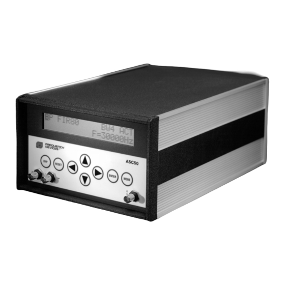
Operation Manual The ASC-50 is a self-contained signal conditioning filter/amplifier instrument that combines Analog and Digital Signal Processing (DSP) capabilities while providing conventional analog signal input and output. Analog and DSP functions are available without the need for computer programming while familiar analog instrument operation is maintained. -
Page 4: Available Types Of Filter Transfer Functions
ASC-50 Operation Manual Available Low-Pass, High-Pass Transfer Functions ANALOG Butterworth 4,6,8,10 Pole Chebychev (0.1dB Ripple) 4,6,8,10 Pole Elliptic-60 dB (0.1dB Ripple) 4,6,8,10 Pole Elliptic-80 dB (0.1dB Ripple) 4,6,8,10 Pole DIGITAL FIR-40 dB FIR-60 dB FIR-80 dB Band-Pass, Band-Reject Transfer Functions... - Page 5 ASC-50 Operation Manual Power-On/Off A two-position toggle switch located on the rear panel turns the AC power on and off. Upon power-on, the front panel will display MODE 1 of the set-up present at the time power was turned off.
-
Page 6: Using The Asc-50
ASC-50 Operation Manual USING THE ASC-50 User Interface User entry is accomplished by means of a “soft front panel” with the user entry prompted by the display. Left ← ← and Right → → Arrows - place the blinking cursor on the function that is to be changed. - Page 7 ASC-50 Operation Manual Mode 1 Field 1 - Filter type Field 4 - Q/Bandwidth A. LP (Low-pass) A. Q2 (Q=2) Does not apply to FIR40, FIR60, B. HP (High-pass) FIR80 C. BP (Band-pass) B. Q5 (Q=5) Does not apply to FIR40, FIR60, D.
-
Page 8: Definition Of Terms
ASC-50 Operation Manual Filter performance characteristics presented to the display are not available for change but rather indicate relative performance of the various filters (See Attachment 2 for plots of the available filter transfer functions). Shape Factor (SF) Used for analog filters to indicate the ratio of corner frequency of the filter to attenuation floor frequency. In the case of Butterworth (Buttr) and Chebychev (Cheby) filters an attenuation level of 80dB is assumed. -
Page 9: Sample Rate Control Explanation And Chart 1
The maximum bandwidth of any DSP system is limited to less than one-half of the sampling frequency. In the case of the ASC-50 the maximum bandwidth is one-quarter of the sampling frequency. In order to provide the highest performance from the available bandwidth the ASC-50 provides an automatic-sampling rate selection control. -
Page 10: Operational Considerations
ASC-50 Operation Manual OPERATIONAL CONSIDERATIONS Anti Alias and Reconstruction Filters The automatic sample control is transparent to the user and operates the internal input anti-alias (AA) and output reconstruction (RC) filters. These filters, operating in cascade, determine the system bandwidth and phase characteristics. - Page 11 DSP Bypass Control The overall frequency response of the ASC-50 is the cascade of the anti-alias and reconstruction filters as well as the DSP filter chosen. DSP Bypass (BYP) allows the operator to remove the DSP filter from the cascade while retaining frequency sampling along with anti-alias and reconstruction filtering.
-
Page 12: Asc-50 Specifications
ASC-50 Operation Manual SPECIFICATIONS (@25 ° C and Rated Power Input) Input Characteristics Impedance 1MΩ || 47pF to Analog Ground (each input) Input Configuration Single Ended or Differential Analog Clipping Indicator Threshold ±10V DC Offset ±5V DC Analog Pre-Gain Range... -
Page 13: Power And Fuzing Instructions
ASC-50 Operation Manual INSTRUCTIONS TO CHANGE VOLTAGE ASC-50 BACK PANEL POWER ENTRY MODULE 1. Disconnect power 2. Remove black plastic cover next to power cord connection. 3. Check fuses and replace blown fuse with 250V fuse. 4. Remove pc-board with white plastic tab and position pc-board and tab for 230V or 240V operating voltage. -
Page 14: Theory Of Operation
ASC-50 Operation Manual Theory of Operation Referring to the block diagram (Figure 2), the operation of the ASC-50 can be explained in terms of the various functional blocks. Anti-Alias Reconstruction Filter Filter (Programmable) (Programmable) Gain Freq Freq Control Analog DIF/SNG... - Page 15 ASC-50 Operation Manual Saturation Detectors Analog and digital saturation detectors are routed from their sources to the display indicators. Anti-alias Filter Limits the input bandwidth to one-fourth of the sampling frequency, preventing corruption from out-of-band signals. Analog to Digital Converter The analog to digital converter (A/D) provides the Digital Signal Processor (DSP) with sampled amplitude data.
- Page 16 ASC-50 Operation Manual Attachment 1 ASC50 Menu 1 of 2 Lowpass and Highpass Filter Menu Options Left or right arrow Filter Number Type of Poles Up or down arrow Buttr Cheby Low-Pass High-Pass Ell60 Ell80 Frequency FIR40 FIR60 FIR80 25 Locust St, Haverhill, Massachusetts 01830 • Tel: 800/252-7074, 978/374-0761 • FAX: 978/521-1839...
- Page 17 ASC-50 Operation Manual Attachment 1 ASC50 Menu 2 of 2 Bandpass and Bandreject Filter Menu Options Left or right arrow Up or down arrow Filter Filter Type Pole Buttr Pairs Cheby Ell60 Ell80 Frequency FIR40 Band-Pass Band-Reject FIR60 FIR80 25 Locust St, Haverhill, Massachusetts 01830 • Tel: 800/252-7074, 978/374-0761 • FAX: 978/521-1839...
-
Page 18: Iir Transfer Function Curves
ASC-50 Operation Manual AVAILABLE IIR TRANSFER FUNCTIONS 4,6,8,10 Pole Butterworth 4,6,8,10 Pole Chebychev 4 Pole 60dB Elliptic -100 -100 -100 5 6 7 8 5 6 7 5 6 7 8 5 6 7 5 6 7 8 5 6 7 10.0... - Page 19 ASC-50 Operation Manual AVAILABLE IIR TRANSFER FUNCTIONS 10 Pole 80dB Elliptic 4,6,8,10 Pole Butterworth 4,6,8,10 Pole Chebychev -100 -100 -100 5 6 7 8 5 6 7 5 6 7 8 5 6 7 5 6 7 8 5 6 7 10.0...
- Page 20 ASC-50 Operation Manual AVAILABLE IIR TRANSFER FUNCTIONS 8 Pole 80dB Elliptic 10 Pole 80dB Elliptic 3PP Butterworth Q2,5,10,20 -100 -100 -100 5 6 7 8 5 6 7 5 6 7 8 5 6 7 5 6 7 8 5 6 7 10.0...
- Page 21 ASC-50 Operation Manual AVAILABLE IIR TRANSFER FUNCTIONS 3PP 60dB Elliptic Q20 4 PP 60dB Elliptic Q2 4 PP 60dB Elliptic Q5 -100 -100 -100 5 6 7 8 5 6 7 5 6 7 8 5 6 7 5 6 7 8 5 6 7 10.0...
- Page 22 ASC-50 Operation Manual AVAILABLE IIR TRANSFER FUNCTIONS 4PP 80dB Elliptic Q2 4 PP 80dB Elliptic Q5 4 PP 80dB Elliptic Q10 -100 -100 -100 5 6 7 8 5 6 7 5 6 7 8 5 6 7 5 6 7 8 5 6 7 10.0...
- Page 23 ASC-50 Operation Manual AVAILABLE IIR TRANSFER FUNCTIONS 4PP Butterworth Q5 4PP Butterworth Q10 4PP Butterworth Q20 -100 -100 -100 Normalized Frequency (Hz) Normalized Frequency (Hz) Normalized Frequency (Hz) 3 PP Chebychev Q2 3 PP Chebychev Q5 3 PP Chebychev Q10...
- Page 24 ASC-50 Operation Manual AVAILABLE IIR TRANSFER FUNCTIONS 4 PP Chebychev Q10 4 PP Chebychev Q20 3PP 60dB Elliptic Q2 -100 -100 -100 Normalized Frequency (Hz) Normalized Frequency (Hz) Normalized Frequency (Hz) 3PP 60dB Elliptic Q5 3PP 60dB Elliptic Q10 3PP 60dB Elliptic Q20...
- Page 25 ASC-50 Operation Manual AVAILABLE IIR TRANSFER FUNCTIONS 4PP 60dB Elliptic Q20 3PP 80dB Elliptic Q2 3PP 80dB Elliptic Q5 -100 -100 -100 Normalized Frequency (Hz) Normalized Frequency (Hz) Normalized Frequency (Hz) 3PP 80dB Elliptic Q10 3PP 80dB Elliptic Q20 4PP 80dB Elliptic Q2...
-
Page 26: Fir Transfer Function Curves
ASC-50 Operation Manual AVAILABLE FIR TRANSFER FUNCTIONS 40dB 63 Tap 40dB 127 Tap 40dB 511 Tap -100 -100 -100 5 6 7 8 5 6 7 5 6 7 8 5 6 7 5 6 7 8 5 6 7 10.0... - Page 27 ASC-50 Operation Manual AVAILABLE FIR TRANSFER FUNCTIONS 40dB 63 Tap 40dB 127 Tap 40dB 511 Tap -100 -100 -100 5 6 7 8 5 6 7 5 6 7 8 5 6 7 5 6 7 8 5 6 7 10.0...
- Page 28 ASC-50 Operation Manual AVAILABLE FIR TRANSFER FUNCTIONS 40dB 63 Tap Q2 40dB 127 Tap Q2 40dB 511 Tap Q2 -100 -100 -100 5 6 7 8 5 6 7 5 6 7 8 5 6 7 5 6 7 8 5 6 7 10.0...
- Page 29 ASC-50 Operation Manual AVAILABLE FIR TRANSFER FUNCTIONS 40dB 63 Tap Q2 40dB 127 Tap Q2 40dB 511 Tap Q2 -100 -100 -100 5 6 7 8 5 6 7 5 6 7 8 5 6 7 5 6 7 8 5 6 7 10.0...
- Page 30 ASC-50 Operation Manual AVAILABLE FIR TRANSFER FUNCTIONS 60dB 63 Tap Q10 60dB 127 Tap Q10 60dB 511 Tap Q10 -100 -100 -100 5 6 7 8 5 6 7 5 6 7 8 5 6 7 5 6 7 8 5 6 7 10.0...
- Page 31 ASC-50 Operation Manual AVAILABLE FIR TRANSFER FUNCTIONS 80dB 63 Tap Q5 80dB 127 Tap Q5 80dB 511 Tap Q5 -100 -100 -100 5 6 7 8 5 6 7 5 6 7 8 5 6 7 5 6 7 8 5 6 7 10.0...
- Page 32 ASC-50 Operation Manual AVAILABLE FIR TRANSFER FUNCTIONS 40dB 63 Tap Q2 40dB 127 Tap Q2 40dB 511 Tap Q2 -100 -100 -100 Normalized Frequency (Hz) Normalized Frequency (Hz) Normalized Frequency (Hz) 40dB 63 Tap Q5 40dB 127 Tap Q5 40dB 511 Tap Q5...
- Page 33 ASC-50 Operation Manual AVAILABLE FIR TRANSFER FUNCTIONS 40dB 63 Tap Q20 40dB 127 Tap Q20 40dB 511 Tap Q20 -100 -100 -100 Normalized Frequency (Hz) Normalized Frequency (Hz) Normalized Frequency (Hz) 60dB 63 Tap Q2 60dB 127 Tap Q2 60dB 511 Tap Q2...
- Page 34 ASC-50 Operation Manual AVAILABLE FIR TRANSFER FUNCTIONS 60dB 63 Tap Q10 60dB 127 Tap Q10 60dB 511 Tap Q10 -100 -100 -100 Normalized Frequency (Hz) Normalized Frequency (Hz) Normalized Frequency (Hz) 60dB 63 Tap Q20 60dB 127 Tap Q20 60dB 511 Tap Q20...
- Page 35 ASC-50 Operation Manual AVAILABLE FIR TRANSFER FUNCTIONS 80dB 63 Tap Q5 80dB 127 Tap Q5 80dB 511 Tap Q5 -100 -100 -100 Normalized Frequency (Hz) Normalized Frequency (Hz) Normalized Frequency (Hz) 80dB 63 Tap Q10 80dB 127 Tap Q10 80dB 511 Tap Q10...
Need help?
Do you have a question about the ASC-50 and is the answer not in the manual?
Questions and answers