Table of Contents
Advertisement
Advertisement
Table of Contents

Related Manuals for ABB PVI-3.0-TL-OUTD


Summary of Contents for ABB PVI-3.0-TL-OUTD
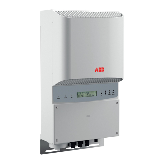
- Page 1 ABB solar inverters Product manual PVI-3.0/3.6/4.2-TL-OUTD (3.0 to 4.2 kW)
- Page 2 Operators are required to read this manual and scrupulously follow the indications reported in it, since ABB cannot be held responsible for damages caused to people and/or things, or the equipment, if the warranty conditions are not observed.
- Page 3 3 - Safety and accident prevention 4 - Lifting and transport 5 - Installation 6 - Instruments 7 - Operation 8 - Maintenance PVI-3.0_3.6_4.2-TL-OUTD-Product manual EN Rev B (M000016BG) EFFECTIVE 09/09/2015 © Copyright 2015 ABB. All Rights Reserved. - 3 -...
-
Page 4: Ntroduction And General Information
ABB accepts no liability for failure to comply with the instructions for correct installation and will not be held responsible for systems upstream or downstream the equipment it has supplied. -
Page 5: Table Of Contents
1- Introduction and general information ontents ntroduction and general information ....................4 Warranty and Supply Conditions ......................4 Not included in the supply .......................4 Contents ..............................5 Reference number index ........................8 Graphical representation of references ....................8 Scope and target audience ........................9 Purpose and document structure ...................9 List of appendix documents ....................9 Operator and maintenance personnel skills/prerequisites .............9 Symbols ad signs ..........................10... - Page 6 1- Introduction and general information ifting and transport ........................35 General conditions ..........................35 Transport and handling .......................35 Lifting .............................35 Unpacking and checking ......................35 List of components supplied ....................36 Weight of the groups of device .....................37 nstallation ............................38 General conditions ..........................38 Environmental checks ......................39 Installations above 2000 metres ...................39 Installation position ........................40...
- Page 7 1- Introduction and general information Description of the menus ........................69 General information ......................69 Statistics Menu ........................71 Settings Menu ........................73 Info Menu ..........................80 AUTOTEST procedure in accordance with standard CEI 0-21 ............81 Running the tests from the display menu ................81 aintenance ............................. 83 General conditions ..........................83 Routine maintenance ......................84 Troubleshooting ........................84...
-
Page 8: Reference Number Index
1- Introduction and general information eference number index , Bracket , Keyboard , RS485 line termination switch , Safety bar , DC Input terminal block , DC Disconnect switch , DSP Reprogramming connectors , AC Output terminal block , Input connectors (MPPT1) , Channel configuration switch , Lower bracket , Input connectors (MPPT2) -
Page 9: Scope And Target Audience
1- Introduction and general information cope and target audience urpose and document structure This operating and maintenance manual is a useful guide that will enable you to work safely and carry out the operations necessary for keeping the equipment in good working order. If the equipment is used in a manner not specified in this manual, the protection provided by the equipment may be impaired. -
Page 10: Symbols Ad Signs
1- Introduction and general information ymbols ad signs In the manual and/or in some cases on the equipment, the danger or hazard zones are indicated with signs, labels, symbols or icons. Table: Symbols This points out that it is mandatory to consult the manual or original do- cument, which must be available for future use and must not be dama- ged in any way. -
Page 11: Field Of Use, General Conditions
1- Introduction and general information ield of use, general conditions ABB shall not be liable for any damages whatsoever that may result from incorrect or careless operations. You may not use the equipment for a use that does not conform to that provided for in the field of use. -
Page 12: Haracteristics
Characteristics eneral conditions A description of the equipment characteristics is provided to identify its main components and specify the technical terminology used in the manual. This chapter contains information about the models, details of the equipment, characteristics and technical data, overall dimensions and equipment identification. -
Page 13: Models And Range Of Equipment
2 - Characteristics odels and range of equipment The specific models of monophase inverters covered by this manual are divided into three groups according to their maximum output power: 3.0 kW, 3.6 kW, or 4.2 kW. For inverters of equal output power the variant between the various mo- dels is the presence or lack thereof of the DC disconnect switch The choice of the inverter model must be made by a qualified technician who knows about the installation conditions, the devices that will be installed outside the inverter and possible... -
Page 14: Identification Of The Equipment And The Manufacturer
3. Rating data 4. Certification marks DIN V VDE 0126-1-1 PROTECTIVE CLASS: I Made in Italy www.abb.com/solar MODEL: SOLAR INVERTER PVI-3.0-TL-OUTD N.B. The labels must NOT be 600 V 230 V 1Ø dc max 90 - 580 V 50 Hz dc MPP hidden with objects and ex- φ... - Page 15 The officially required information is located on the approval label. The identification label is an accessory label which shows the information necessary for the identification and cha- racterisation of the inverter by ABB. N.B. The labels must NOT be hidden with objects and extraneous parts (rags, boxes, equip- ment, etc.);...
-
Page 16: Characteristics And Technical Data
2 - Characteristics haracteristics and technical data Table: Technical Data PVI-3.0-TL-OUTD PVI-3.6-TL-OUTD PVI-4.2-TL-OUTD Input Absolute Maximum Input Voltage (V 600 V max,abs Rated Input Voltage (V 360 V Input start-up voltage (V 200 V (adj. 120...350 V) start Input operating interval (V ...V... - Page 17 3. The output frequency range may vary according to the grid standard of the country of installation 4. Refer to the document “String inverter – Product Manual appendix” available at www.abb.com/solarinverters to know the brand and the model of the quick fit connector Note.
-
Page 18: Tightening Torques
2 - Characteristics ightening torques To maintain the IP65 protection of the system and for optimal installa- tion, the following tightening torques must be used: M25 (ring nut fixing) AC cable gland 5.0 Nm M25 (locknut fixing) AC cable gland 7.5 Nm M20 (ring nut fixing) Service cable glands... -
Page 19: Bracket Dimensions
2 - Characteristics racket dimensions The wall mounting bracket dimensions are expressed in mm and inches 2.39” 60.8mm 1.18” 1.16” 30mm 29.5mm 0.31” 0.39” 10mm 0.87” 22mm 4.33” 110mm - 19 -... -
Page 20: Efficiency Curves
Graphs of the efficiency curves of all models of inverter described in this manual are shown below. The efficiency curves are linked to technical parameters that are continually being developed and improved and should therefore be considered approximate. PVI-3.0-TL-OUTD PVI-3.0-TL-OUTD - Efficiency Curves PVI-3.0-TL-OUTD-S 200Vdc 360Vdc 480Vdc...
Need help?
Do you have a question about the PVI-3.0-TL-OUTD and is the answer not in the manual?
Questions and answers