Advertisement
Quick Links
RPK3E - Remote Ready "EASY" Control
General Assembly, Installation, and Operation Instructions for use with Natural Gas Burners;
ATTENTION! READ INSTRUCTIONS CAREFULLY BEFORE ASSEMBLY
INSTALLER: LEAVE THIS MANUAL WITH THE APPLIANCE ● CONSUMER: RETAIN THIS MANUAL FOR FUTURE REFERENCE
Adjustable Wrench, Pipe Wrench, Flat Head Screwdriver, Phillips Screwdriver, Pipe Sealing compound
(Only required if fittings not already prepared with pre-wrapped Teflon thread tape).
1. Air Mixer for LP Gas Burner Inlet Assembly (MA2)
2. Burner Orifice #53,49 and 45 (01-XX)
3. Internally Tapped 3/8 Flared x 3/8 MIP Elbow (A2T)
4a. Pilot Support Bracket for F & TNA burners (PB-1)
4b. Pilot Support Bracket for CS & CXF burners (PB-2)
5. 10-32 x 3/8 bolts (qty. 3)
6. 10-32 Hex nut (qty 1)
1
2
3
9
WIRELESS REMOTE OPTIONS
(each sold separately)
Wireless On/Off
Wireless Wall
Remote with
Thermostat
Thermostat
(TS-2R)
(THR-2R)
What sets Rasmussen Safety Pilot Kits apart from those of other manufacturers, aside from quality, is the ease and affordability with
which our valve can be upgraded from manual operation to one of several remote control devices!
F, FX, CS, CXF, TNA or Propane Gas Burners: FA, FAX, CA, CXFA, TNA/LP
12028 E. PHILADELPHIA ST. WHITTIER CA 90601 U.S.A.
REQUIRED TOOLS AND MATERIALS
RPK3E PARTS LIST
4A
(Green mark indicates Natural Gas,
Red indicates Propane Gas)
11
Wireless Wall
Wireless Wall Timer
Switch
(30/60/120 Minutes)
(WS-2R)
(WT-2R)
www.rasmussen.biz
7. Valve Plug ( used when replacing, servicing or
upgrading Motor Drive) (VALVE PLUG EASY).
8. Valve Knob Extender (STV-KE2)
9. "EASY" Safety Valve (STV-10) & Heat shield
(HS-ST1)
10. Pilot Thermocouple Assembly (J95R -NG or -LP)
11. 10" flex Connector (SSCB-10)
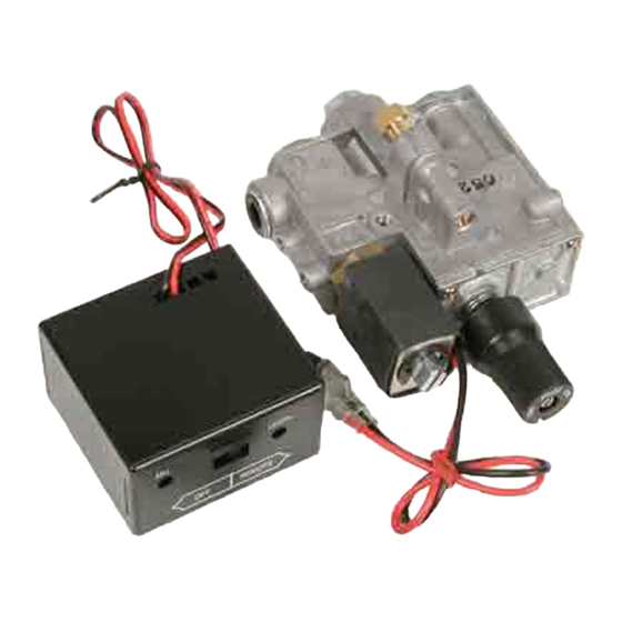
12. Remote Receiver (BPR2)
Ceramic Log House (RH2) (Sold Separately)
13.
4B
5
10
"RE" "Variable Flame Height" Remote Control
Kit to upgrade from "ME" or "SE" to "RE" functionality.
Includes: DC Motor Drive, Receiver, Transmitter
Battery Pack/Receiver
(BPR-2)
HI/LO DC
Motor Drive
(STV-VMD)
1
LISTED BY
LISTING NO. 1180
FORM: RPK3E-9-06
7
6
8
12
UPGRADE OPTION
Upgrade Kit (RE-UP1)
and batteries.
Variable Flame Height Remote Control
Transmitter (STR-RMD)
13
Advertisement

Summary of Contents for Rasmussen RPK3E
- Page 1 Variable Flame Height Remote Control Transmitter (STR-RMD) What sets Rasmussen Safety Pilot Kits apart from those of other manufacturers, aside from quality, is the ease and affordability with which our valve can be upgraded from manual operation to one of several remote control devices!
- Page 2 ASSEMBLY STEP ONE: BURNER PAN FITTINGS (Figure 1) NOTE: If fittings do not come pre-wrapped with Teflon threaded tape, pipe compound must be applied to the non-flared threads. 1. Ensure that the BURNER PLUG (Figure 1A.) is inserted into the opposite end of the BURNER PIPE (Figure 1B) and wrench tightened.
- Page 3 FIGURE 4 (CXF AND CXFA Burners FIGURE 5 (TNA / TNA-LP Burners) 10-32 bolts 10-32 nuts & bolts Pilot Thermocouple Assembly Pilot Thermocouple Assembly FIGURE 6 STEP THREE: CONNECT BURNER AND PILOT GAS SUPPLY Connect 10” FLEX CONNECTOR (Figure 6A) between the flared ends of the VALVE OUTPUT 3/8 FLARED FITTING (Figure 6B) and the BURNER INPUT 3/8 FLARED 3/8 x C) BURNER INPUT...
- Page 4 WARNING DO NOT remove Heat Shield (Figure 7A) . It is intended to prevent premature valve failure and voiding of • warranty. Replace immediately if removed for any reason. The “EASY” Safety Control Valve must be protected to a maximum ambient temperature of 225° F. •...
- Page 5 FURTHER SAMPLES OF FIREBOX LAYOUT Each shown with “EASY” Safety Valve and Receiver placed as far forward and to the side of the burner pan as possible. TNA STYLE BURNER Internally Tapped 3/8 Flared x 3/8 Pilot Thermocouple Assembly MIP Elbow Burners Flex Connector Heat Shield...
- Page 6 IMPORTANT! CHIMNEY DAMPER MUST BE WIDE OPEN! THE FLUE MUST VENT ALL PRODUCTS OF COMBUSTION. DAMPER AND GLASS DOORS MUST BE FULLY OPEN BEFORE LIGHTING OR BURNING FOR PROPER VENTILATION AND TO PREVENT HEAT DAMAGE TO VALVE. NOTE: The VALVE KNOB has complete control of gas to the pilot and burner. It cannot be turned to “OFF” without first depressing dial to the “PILOT “...
Need help?
Do you have a question about the RPK3E and is the answer not in the manual?
Questions and answers