Table of Contents
Advertisement
Quick Links
Ing. J. de Wijs.
Populierstraat 44,
4131 AR Vianen,
the Netherlands
Tel/Fax. +31 (0)347-372242
e-mail: info@dewijs-3d.com
Website: www.dewijs-3d.com
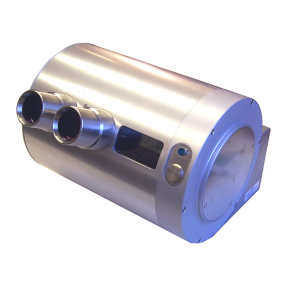
User manual of the 10 slide rotary viewer model 2007
Design and production of stereoscopic instruments.
motor advance mechanism
The contents are subject to changes without giving notice. Last update May 2007
Bank: Postbank account: 6084601,
Swiftcode: INGBNL2A
Bank code: NL24PSTB0006084601
Tax number: NL 1899.16.084 B01
K.v.K. Reg. Nº 23071201 Utrecht
Advertisement
Table of Contents

Summary of Contents for de Wijs 2007
- Page 1 Design and production of stereoscopic instruments. Tax number: NL 1899.16.084 B01 K.v.K. Reg. Nº 23071201 Utrecht User manual of the 10 slide rotary viewer model 2007 motor advance mechanism The contents are subject to changes without giving notice. Last update May 2007...
-
Page 2: Table Of Contents
Contents INTRODUCTION ..................3 1. FIRST INDICATIONS FOR OPERATIONAL USE ......3 1.1 O ..........3 PENING THE VIEWER FOR EXCHANGING THE SLIDES 1.2 W ?................4 ERE DO PLACE THE VIEWER 1.3 H ? ........... 4 OW DO MOUNT THE VIEWER AGAINST A WALL 2. -
Page 3: Introduction
Each change in the previous models extended the durability, stability and the quality. Especially this 10-slide rotary viewer 2007 has been adapted for the demand to show short 3D slide series to large amounts of public to be informed. To give any idea about the changes with respect to the previous model: The CCFL is more protected against damaging when inserting the slide drum. -
Page 4: Were Do Iplace The Viewer
1.2 Were do I place the viewer? Obviously you already have chosen a spot for the viewer in your museum, exhibition or other public environment. Here are some considerations that might help you to check the spot; − Keep in mind the height of the viewer. Children and grown-ups both want to look in the viewer! −... -
Page 5: Manual Operation (Without Pc Control)
2. Manual operation (without PC control) In this situation, the rotary viewer is used in stand-alone mode, without any external devices. 2.1 Four operational modes: The rotary viewer is able to work in 4 different modes. These modes are configurable using the small switches inside the viewer. -
Page 6: External Control (With Pc)
4.1 Setting up the equipment and cable connections List of materials: − 10 slide Rotary viewer of ‘de Wijs’ model 2003 − One 12 Volts dc adapter for the rotary viewer. − Language panel (if you need it). -
Page 7: Data
6 Data 6.1 Technical specifications of the rotary viewer Slides: • Slide frame format; 41x101 mm. • Maximum picture size; 23x33 mm. • Compatible with RBT frames, mounted between glass maximum 3 mm. Thickness. • The drum can hold 10 slides and accompanying text cards (cut to size 42x74 mm.) Optics: •... -
Page 8: External Connection Diagram
6.2 External connection diagram SW1: lamp turn-off delay active down- lamp always on adapter: SW2: front button passes signal to external device. 12 Volts d.c. down- front button directly controls viewer 1,5A SW3: after lamp turns off, nothing happens stabelized down- after lamp turns off, drum goes to slide Nº... -
Page 9: Connections Of The D25 And J3 Connector
6.3 Connections of the D25 and J3 connector. D25 connector: Connector Description computer side Description rotary viewer Direction looking from and addressing side computer side. Strobe Base+2 bit 0 Not used Output Base+0 bit 0 Change slide, 1= moving Output Base+0 bit 1 Lamp, 1=lamp on. -
Page 10: Electronic Component List Model 06-02-A-M
6.4 Electronic component list model BC547b 06-02-A-M U1 4081 Quad And U2 Relais 2x 12V OMRON G2R-2 U3 LM555 timer IC 10K 1/4 Watt IR detect U4 Relais 1x 12V OMRON G5V-1 10K 1/4 Watt IR detect U5 4071 Quad Or 100K 1/4 Watt U6 LM7805 1A 10K 1/4 Watt... -
Page 11: Internal Electrical Connection Diagram
6.5 Internal electrical connection diagram. Optical switches top view ccfl inverter blinking Drum Front panel button Motor 12Vdc 500mA 2.1 mm plug... -
Page 12: Electronic Schematics
6.6 Electronic schematics... -
Page 13: Pcb Layout
6.7 PCB layout...
Need help?
Do you have a question about the 2007 and is the answer not in the manual?
Questions and answers