Table of Contents
Advertisement
Quick Links
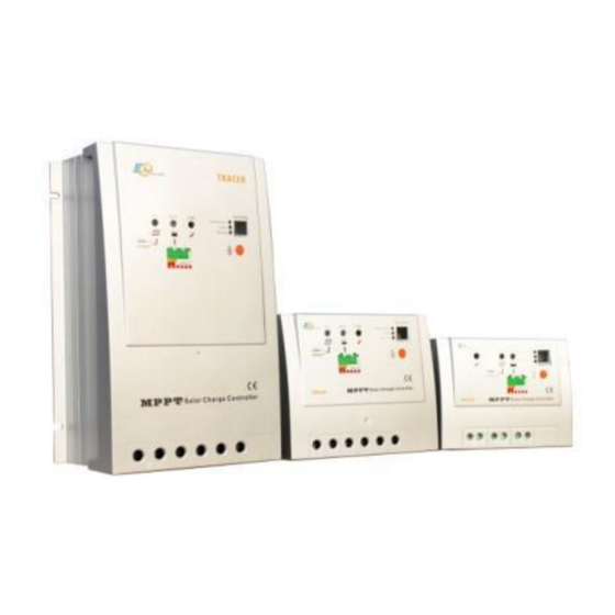
MPPT Solar Controller
Characteristics
MPPT series controller is suitable for the street light
system. The controller features a smart tracking algorithm
inside that maximizes the energy from the solar PV
module(s) and charge the battery. At the same time, the
low voltage disconnect function (LVD) will prevent the
battery from over discharging.
The controller charging process has been optimized for
long battery life and improved system performance. The
comprehensive self-diagnostics and electronic protection
functions can prevent damage from installation mistakes
or system faults.
Peak conversion efficiency of 97 %, high Tracking
efficiency of 99%.
Very fast sweeping of the entire I-V curve, several
seconds tracking speed.
Widely used, automatic recognize day/night.
Timer function with 1-15 hours option for street light.
Unique dual timer function, enhance the flexibility of
street light system.
Sealed, Gel and Flooded battery option.
Adopting temperature compensation and correcting the
charging and discharging parameters automatically,
improving the battery lifetime.
Electronic protection: over charging, over discharging,
overload, short circuit.
Reverse protection: any combination of solar module
and battery, without causing damage to any component.
RJ45 interface with remote meter MT-5, convenient to
check operating parameters of controllers. ( MT-5 is
optional)
PLURIGÁS SOLAR ENERGIAS Lda. - End: Urb. António Aleixo -1 , 4820-358 Fafe, Portugal
1
Tel : +351 253700060 - Fax : +351 253700065 – Site: www.plugassolar.pt – Email: geral@plurigassolar.pt
Advertisement
Table of Contents

Related Manuals for BlueSun 10 A

Summary of Contents for BlueSun 10 A
- Page 1 MPPT Solar Controller Characteristics MPPT series controller is suitable for the street light system. The controller features a smart tracking algorithm inside that maximizes the energy from the solar PV module(s) and charge the battery. At the same time, the low voltage disconnect function (LVD) will prevent the battery from over discharging.
-
Page 2: Technical Specifications
1. Technical Specifications Model 10 A 20 A 30 A 45 A Rated Battery Current 10 A 20 A 30 A 45 A Nominal System Voltage 12V / 24V Auto Work Max. Solar Input Voltage 100 V 150 V Maximum Battery Voltage... - Page 3 1. Technical Specifications 1 – Temperature Sensor Measure ambient temperature and make temperature compensation for charging and discharging. 2 – Charging Status LED Indicator An LED indicator that shows charging status and overvoltage of battery. 3 – Battery Status LED Indicator An LED indicator that shows battery status or system errors. 4 –...
-
Page 4: Installation Instructions
Installation Instructions Read through the entire installation section first before beginning installation. Be very careful when working with batteries. Wear eye protection. Have fresh water available to wash and clean any contact with battery acid. Uses insulated tools and avoid placing metal objects near ... - Page 5 Installation Instructions 2.2. WIRING NOTE: A recommended connection order has been provided for maximum safety during installation. The Controller is a negative ground controller. Any negative connection of solar module, battery or load can be earth grounded as required. Grounding is recommended. CAUTION: Don’t connect the loads with surge power exceeding the ratings of the controller.
-
Page 6: Operation
Operation 3.1. MPPT Technology 3.1.1. MPPT The Controller utilizes Maximum Power Point Tracking technology to extract maximum power from the solar module (s). The tracking algorithm is fully automatic and does not require user adjustment, Controller technology will track the array maximum power point voltage (Vmp) as it varies with weather conditions, ensuring that maximum power is harvested from the array through the course of the day. - Page 7 3. Operation 3.1.2 Battery Charging Information The Controller has a 4-stage battery charging algorithm for rapid, efficient, and safe battery charging. Bulk Charge In this stage, the battery voltage has not yet reached boost voltage and 100% of available solar power is used to recharge the battery.
-
Page 8: Led Indications
3. Operation 3.2. LED Indications GREEN ON: charging GREEN BLINK: Battery over-voltage RED: LED digital tube displays ”P” =>‖PV Overvoltage RED: LED digital tube displays ”CP” =>‖PV Overcurrent GREEN ON when battery voltage in normal range GREEN FLASHING when battery full ORANGE ON when battery under voltage RED ON when battery over discharged Please refer to Chapter 5 for troubleshooting. -
Page 9: Battery Type
3. Operation LED Nº TIMER 1 LED Nº TIMER 2 Dusk to Dawn, Load will be on all night Sem atraso, a carga é ligada após anoitecer Load will be on for 1h after 10 min delay since sunset. Load will be on for 1 hour before sunrise Load will be on for 2h after 10 min delay since sunset. -
Page 10: Troubleshooting & Maintenance
4. TROUBLESHOOTING / MAINTENANCE Indicador Razões Possivéis Troubleshooting Charging LED indicator off during PV array disconnection Check that PV and battery wire connections are daytime when sunshine falls on PV correct and tight. modules properly. Green charging LED indicator Battery voltage higher than over voltage Check if battery voltage over high.
Need help?
Do you have a question about the 10 A and is the answer not in the manual?
Questions and answers