Table of Contents
Advertisement
Quick Links
Advertisement
Table of Contents

Related Manuals for CUSTOM TRUCK LOAD KING SR-4020

Summary of Contents for CUSTOM TRUCK LOAD KING SR-4020
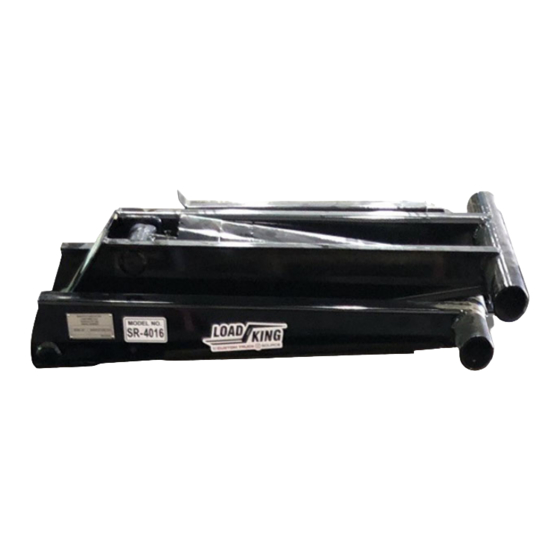
- Page 1 OWNER’S MANUAL LOAD KING SR‐4020 REV A OCTOBER 7, 2020...
-
Page 3: Table Of Contents
Table of Contents REVISION HISTORY ......................4 INTRODUCTION ........................5 DEFINITIONS USED IN THIS MANUAL .................. 6 HOIST CAPACITY ........................7 OPERATORS MANUAL ......................8 1. PRE‐USE INSPECTION ....................8 2. PROPER OPERATION SEQUENCE .................. 8 2.1) TO DUMP ......................8 2.2) USING HOIST’S BODY PROP ................. -
Page 4: Revision History
REVISION A REVISION HISTORY NAME DATE DESCRIPTION OF CHANGE REV. J Haas 10/7/2020 INITIAL RELEASE... -
Page 5: Introduction
Beginning in February of 2015, three family‐owned and operated companies (Custom Truck & Equipment, U lity Fleet Sales and Forestry Equipment of VA) joined together to form what is now Custom Truck One Source. Shortly a er its incep on, UCO Equipment became a part of the CTOS family along with TNT Equipment six months later. -
Page 6: Definitions Used In This Manual
REVISION A DEFINITIONS USED IN THIS MANUAL The following table describes text and symbols used to highlight important informa on. Signal Word Symbol Explanation Danger is used to alert readers about an immediate and serious hazard that will likely be DANGER fatal. -
Page 7: Hoist Capacity
REVISION A HOIST CAPACITY NOTE: This chart is a reference to determine the capacity of your hoist based on overhang. BDOY LENGTH REAR OVERHANG CAPACITY AT 50° (in) (in) (Tons) 12.8 11.5 10.3 12.8 11.5 Moun ng Heigh/Min Longsill Height = 9.6” / 5” Moun ng Distance = 71.5”... -
Page 8: Operators Manual
REVISION A OPERATORS MANUAL When using a Load King Scissor Hoist, it is important to have a good understanding of the proper pre‐ Inspec on, post‐inspec ons, and opera ng guidelines. By following these steps, you can safely operate the Load King Scissor Hoist with minimal risks of damage to the machine or the surrounding property. -
Page 9: Using Hoist's Body Prop
REVISION A OPERATORS MANUAL (Cont.) DANGER: NEVER place arms, hands, or other body parts under the hoist while running. NEVER allow anyone under the hoist while in the raised posi on without the hoist securely res ng on the body prop. Before lowering the hoist, ALWAYS ensure no people, animals, tools, or other debris are under the body. -
Page 10: Post Operation Inspection
REVISION A OPERATORS MANUAL (Cont.) 3. POST OPERATION INSPECTION: 1. Complete a 360 degree walk around to ensure there has been no hydraulic leaks during opera on. 2. Visually inspect all cri cal components and fasteners to ensure they were not damaged or loosened during opera ons. - Page 11 REVISION A SAFETY INFORMATION (Cont.) DANGER: Do not move truck with bed in the upright posi on, or without the tailgate latched. Doing so could lead to collisions with overhead obstacles or dangerous shi ing of loaded materials. WARNING: Do not overload. Be mindful of Gross Vehicle Weight Ra ng of your truck, as well as local laws regarding vehicle weight in your area.
-
Page 12: Parts Breakdown
REVISION A PARTS BREAKDOWN... - Page 13 REVISION A PARTS BREAKDOWN (CONT.) ITEM NO. PART NUMBER DESCRIPTION 1030908 WELDMENT, FRAME SCISSOR HOIST SR-4020 1030931 WELDMENT, SCISSORS HOIST SR-4020 1030932-1 LOWER PIVOT ARM SHAFT 1031007 WELDMENT, PROP ROD SR-4020 1031006 WELDMENT, BODY LIFTING FOOT UOS-001306 TUBE SPACER COLLAR 98306A393 STEEL CLEVIS PIN—1/2”...
-
Page 14: Installation
REVISION A INSTALLATION 1. Install lower pivot arm sha (1) into the lower tube of the scissor hoist (2), as shown below. 2. Insert the hoist’s lower pivot arm (1) into the channels on the subframe (2), and secure them with the proper hardware. - Page 15 REVISION A INSTALLATION 3. Weld the 3/8” spacer as shown below, posi oned as far forward on the subframe rail as possible. 4. If necessary, the frame extensions 1034528 and 1034529 (see breakdown on page 12‐13) can be added to the subframe.
- Page 16 REVISION A INSTALLATION 6. Using the diagrams below, locate the ideal moun ng angle loca on that best fits your applica on. 7. Drill two holes in the chassis frame and bolt the moun ng angles as shown below.
- Page 17 REVISION A INSTALLATION 8. Weld the moun ng angles to the subframe rail as shown below. Ensure that the moun ng angle is welded to the subframe in the “CRITICAL WELD AREA” located below the lower pivot arm, as shown in the image below.
- Page 18 REVISION A INSTALLATION 10. Slide the spacer collar (1) onto the sha of the body li foot (2), and slide the li foot’s sha into the upper hoist tube (3). Repeat on the other side of the hoist. 11. Install the body guide plates on both sides of the subframe, in one of the two loca ons shown below.
- Page 19 REVISION A INSTALLATION 12. Place the frame rails of the body onto the hoist subframe. Posi on the body in the correct loca on and weld the subframes rear pivots to the frame rails of the body as shown below. 13.
-
Page 20: Lubrication And Maintenance
REVISION A LUBRICATION AND MAINTENANCE Lubricate grease zerks in all loca ons shown below (8 total). Loca ons indicated with red arrows below CAUTION: ALL grease zerks are to be topped off prior to first use and every month following. -
Page 21: Load King Scissor Hoist Labels
REVISION A LOAD KING SCISSOR HOIST LABELS... - Page 22 REVISION A LOAD KING SCISSOR HOIST LABELS (Cont.) ITEM NO. PART NUMBER DESCRIPTION QTY. 1034551 PLACARD, DANGER DEATH/SERIOUS INJURY 1034552 PLACARD, HOIST GREASE LOCATIONS 1034553 PLACARD, DANGER BODY PROP INSTRUCTIONS 1034554 PLACARD, DANGER STAND CLEAR WHILE OPERATING 1034555 PLACARD, WARNING SERVICING REQUIREMENTS 1034556 PLACARD, LOAD KING LOGO 1034557...
-
Page 23: Load King Warranty
REVISION A LOAD KING WARRANTY Load King (herein a er referred to as the COMPANY) warrants all products manufactured by it and purchased by you to be free from defects in material and manufacture at the me of shipment, for one (1) year from date of delivery. The COMPANY will furnish replacements for such parts as the COMPANY finds to have been defec ve at the me of delivery or, at the COMPANY’s op on, will make or authorize repairs to such parts, provided that, upon request, such parts are returned, transporta on is prepaid to the factory from which they were shipped. This warranty shall not apply to any Product which has been subjected to misuse, misapplica on, overloading, neglect (including but not limited to use of unauthorized parts or a achments), adjustments or repair. Engines, motor, res, wheels, suspensions, axles, etc. and any accessories furnished with or used in the COMPANY’s products, but which are not manufactured by the COMPANY, are not warranted by the COMPANY but are sold only with the express warranty, if any, or the manufacturers thereof. This warranted is limited to the first purchaser/user and is not transferable. THE FOREGOING IS IN LIEU OF ALL OTHER WARRANTIES, WHETHER EXPRESSED OR IMPLIED (INCLUDING, WITHOUT LIMITATIONS, OF MERCHANTABILITY AND FITNESS OF ANY PRODUCT FOR A PARTICULAR PURPOSE), AND OF ANY OTHER OBLIGATION OR LIABILITY ON THE PART OF THE COMPANY. -
Page 24: Load King Warranty Data Record
REVISION A LOAD KING WARRANTY DATA RECORD Scissor Hoist Warranty Form Submission Date Date of Delivery Model Number Dealer Address Customer Address Record this informa on at the me that warranty registra on form is completed and returned to Load King... - Page 25 Load King PO Box 427 Elk Point, South Dakota, USA 57025‐0427 Toll Free: (888) 264‐5522...
Need help?
Do you have a question about the LOAD KING SR-4020 and is the answer not in the manual?
Questions and answers