
Subscribe to Our Youtube Channel
Related Manuals for ARRI VMM-1

Summary of Contents for ARRI VMM-1
- Page 1 VMM-1 VMM-1 Video Monitor Multicam 1 Video Monitor Multicam 1 U S E R U S E R M A N U A L M A N U A L June 10, 2020 June 10, 2020...
- Page 2 Original version. For Further Assistance Arnold & Richter Cine Technik GmbH & Co. Betriebs KG Herbert-Bayer-Str. 10 D-80807 Munich Germany E-mail: service@arri.com www.arri.com/en/technical-service Document Revision History Document ID: D45 10005351 Version Release Date v1.0...
-
Page 3: Table Of Contents
Contents Contents Contents..........................3 Disclaimer.......................... 4 Scope of Delivery and Warranty..................5 Safety Guidelines......................6 Monitor Layout........................7 Monitor Connectors......................9 Front Controls......................... 10 OSD Keypad and Menu Operation................12 Monitor Menu........................13 Main Menu........................13 Options Submenu......................15 Hotkeys and Quickmenu....................16 Info Pages........................17 Appendix.......................... -
Page 4: Disclaimer
In no event shall ARRI or its subsidiaries be liable for or have a remedy for recovery of any special, direct, indirect, incidental, or consequential damages, including, but not limited to lost profits, lost savings, lost... -
Page 5: Scope Of Delivery And Warranty
The VMM-1 is manufactured by Baytek Industriesysteme GmbH. Leipziger Straße 4 85386 Eching Deutschland https://www.baytek.de/ Warranty For scope of warranty, please ask your local ARRI Service Partner. ARRI is not liable for consequences from inadequate shipment, improper use or third-party products. -
Page 6: Safety Guidelines
► Heed all warnings on the system and in the safety and operating instructions before you operate or install the system. Follow all installation and operating instructions. ► Do not use accessories or attachments that are not recommended by ARRI, as they may cause hazards and invalidate the warranty. -
Page 7: Monitor Layout
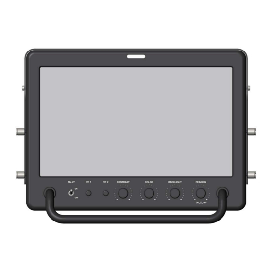
Monitor Layout Monitor Layout Monitor Front 10" Display Operator Tally LED Tally Switch VF 1 User Button VF 2 User Button CONTRAST Dial COLOR Dial BACKLIGHT Dial PEAKING Dial Monitor Top OSD Keypad Moderator Tally LED Monitor Bottom PWR Power Connector TALLY In Connector CAMERA Connector SDI In Connector... - Page 8 Monitor Layout Monitor Rear Moderator Tally LED Camera No. Display...
-
Page 9: Monitor Connectors
The PWR connector is the main power input of the VMM-1 and accepts an input voltage range from 9.0 to 32.0 V DC. Using the VMM-1 Power Cable (K2.0037711), connect the monitor to the 12 V 2-pin LEMO power output of the ARRI AMIRA. -
Page 10: Front Controls
20. Note that operability is still guaranteed with low backlighting. PEAKING Dial With the use of the PEAKING dial, the ARRI camera peaking can be activated and controlled via the monitor. The camera supports two peaking modes, Color Peaking (default) and Aperture Peaking. For more information please refer to the camera user manual. - Page 11 Front Controls 3. With peaking activated, rotate the dial to set the peaking strength in a range of 1 to 20. Note: Peaking adjustment is only functional when the monitor's signal source is set to Camera. Note: If the peaking status is changed remotely in the camera, the status is only updated after reopening the control overlay or by rotating the dial.
-
Page 12: Osd Keypad And Menu Operation
OSD Keypad and Menu Operation OSD Keypad and Menu Operation Power Button Power LED [UP] / + Button [DOWN] / - Button [LEFT] Button [RIGHT] / M Button Power Button and Power LED The power button enables the monitor to be switched on/off independently of the camera. The green power LED lights up when the monitor is active and is off when the monitor is off or the power supply was interrupted. -
Page 13: Monitor Menu
Monitor Menu Monitor Menu Main Menu Signal Source The Signal Source menu is used to select the image input. 1. Press the [RIGHT] / M button to access the monitor menu. 2. Select menu entry Signal Source. The Signal Source sub menu offers the following options: If AutoScan is switched on, the monitor starts scanning the inputs starting AutoScan with the camera input. - Page 14 Monitor Menu This function allows a vertical mirroring of the screen contents. For a 180° V-Mirroring picture rotation, please set the vertical and horizontal mirroring functions to “ON”. Note: Settings Autoadjust, Tracking, Phase and Position X/Y are not sup- ported. 3.
-
Page 15: Options Submenu
Monitor Menu This switch resets the monitor settings to default values: Default Values Signal Brightness Camera No. Single Contrast Camera No. Active Contrast Camera No. Brightness Single Contrast Tally Moderator Backlight Brightness Tally Operator H + V Mirror Autoscan Aspect Ratio Signal Input Camera X, Y Position... -
Page 16: Hotkeys And Quickmenu
Monitor Menu Set the brightness of the camera number display on the monitor rear in a Brightness range of 0 to 20. If the brightness is set to 0, the display is switched off. 3. Configure the camera number display to your preference. Tally LED The Tally LED submenu offers to configure the brightness for the moderator tally LED on the monitor rear and the operator tally LED on the monitor front. -
Page 17: Info
Monitor Menu Quickmenu The Quickmenu provides convenient access to control common monitor setings. Backlight Brightness: The brightness value can be adjusted using the [UP] or [DOWN] buttons. The menu item is automatically closed after approximately 15 seconds. Info Pages Input Info The Input Info window provides information on the selected input signal, including the maximum image refresh rates (vertical frequency). -
Page 18: Appendix
Appendix Appendix 10.1 Technical Data LCD Type Active Matrix Liquid Crystal Display (AM-LCD) Amorphous silicon TFT (Thin Film Transistor) LED Backlight Aspect Ratio 16:9 Active Screen Size 220.32 x 123.93 mm / 16.063 x 12.047" Ø 508 mm / 20.1" Screen Resolution 1920 x 1080 pixel Pixel Arrangement... -
Page 19: Connector Pin-Outs
Appendix 10.2 Connector Pin-Outs Note: Pin-outs appear as seen by the user. Connector ID: LEMO EEG.0B.302.CLN.A365 TALLY IN Connector ID: DE9 Female Tally RED RxD (Service) TxD (Service) N.C. Tally GREEN N.C. 10.3 Declaration of Conformity FCC Compliance Statement Class A Statement: This equipment has been tested and found to comply with the limits for a Class A digital device, pursuant to part 15 of the FCC Rules. -
Page 20: Accessories
Appendix 10.4 Accessories Mounting Option The VMM-1 can be mounted to the camera using the ARRI Monitor Yoke Support MYS-1 (sold separately). Monitor Yoke Support MYS-1 (K2.0037636) The Monitor Yoke Support MYS-1 is designed specifically around the ARRI VMM-1 multicam monitor. It offers four points of adjust-... -
Page 21: Dimensional Drawings
Appendix 10.5 Dimensional Drawings... - Page 22 Appendix All measurements in mm.
Need help?
Do you have a question about the VMM-1 and is the answer not in the manual?
Questions and answers