Samsung RL44Q Series Service Manual

Samsung RL44Q Series Service Manual

Bottom mounted freezer type
Table of Contents

Advertisement

REFRIGERATOR
RL44Q/F
RL44/41W
RL41/38H
RL44/41P
RL44/41/38E
For the latest information, Please access to our service web site
(•North America : http://service.samsungportal.com •Latin America : http://latin.samsungportal.com
•CIS : http://cis.samsungportal.com •Europe : http://europe.samsungportal.com
•China : http://china.samsungportal.com •Asia : http://aisa.samsungportal.com
•Mideast & Africa : http://mea.samsungportal.com
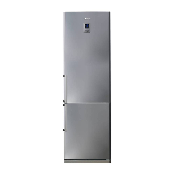
REFRIGERATOR
BOTTOM MOUNTED FREEZER TYPE
BASIC MODEL : RL44Q *
MODEL NAME : RL44Q * /E * /S * /W * /F * /P *
PRODUCT FEATURE
● High Efficiency A+
● Easy Open Handle
● CoolSelect Zone
● Digital Temperature Display
RL44/41/38S
RL41H * /E * /S * /W * /P *
RL38H * /E * /S *
TM

Advertisement

Table of Contents
loading

Summary of Contents for Samsung RL44Q Series

  • Page 1 REFRIGERATOR BOTTOM MOUNTED FREEZER TYPE BASIC MODEL : RL44Q * MODEL NAME : RL44Q * /E * /S * /W * /F * /P * RL41H * /E * /S * /W * /P * RL38H * /E * /S * REFRIGERATOR PRODUCT FEATURE ●...
  • Page 2 The manufacturer or dealer cannot be responsible for the interpretation of this information. SAMSUNG ELECTRONICS AMERICA, INC. Technical Service Guide Copyright ⓒ2008 All rights reserved. This service guide may not be reproduced in whole or in part in any form without written permission from the SAMSUNG ELECTRONICS Company.
  • Page 3 Contents 1. PRECAUTIONS (SAFETY WARNINGS) 2. PRODUCT SPECIFICATIONS 3. DISASSEMBLY AND REASSEMBLY 4. TROUBLE SHOOTING 5. EXPLODED VIEW & PARTS LIST 6. PCB DAIGRAM 7. WIRING DIAGRAM 8. CIRCUIT DIAGRAM 9. REFERENCE INFORMATION...
  • Page 4 1. PRECAUTIONS (SAFETY WARNINGS) ● Upon electronic Control system repair/change, make sure the set unplugged. Be ware of electric shock. ● Use rated electronic Control equipment. Make sure to check out ModeL name, Rated voltage, Rated current, Operation Temp, etc. ●...
  • Page 5 PRECAUTIONS(SAFETY WARNINGS) Read all instructions before repairing the product and keep to the instructions in order to prevent danger or property damage. CAUTION/WARNING SYMBOLS DISPLAYED SYMBOLS means Prohibition”. Indicates that a danger of death means Do not disassemble”. Warning or serious injury exists.
  • Page 6 PRECAUTIONS(SAFETY WARNINGS) ❈ Please ler users know following warnings & cautions in detail. Warning & Caution Do not allow users to store narrow and Do not allow users to store Do not allow users to put bottles or kinds of lengthy bottles or foods in a small multi- pharmaceutical products, scientific glass in the freezer.
  • Page 7 2. PRODUCT SPECIFICATIONS 2-1. Model Specification ·······················8 2-2. View of Fridge & Freezer·····················9 2-3. Comparison with Competitor ··················10 2-4. Electiric Part Specification ···················11 2-5. Dimension(mm) ························13...
  • Page 8 PRODUCT SPECIFICATIONS 2-1) Introduction of main function SAMSUNG refrigerator has the following characteristics. ● ● Characteristics Specification • This products protects the environment by using the R600a refrigerant Environment-friendly and the cyclopentane blowing agent fridge/freezer using R600a • Properties :ODP(Ozone Depletion Potential):0GWP :Lowest...
  • Page 9 PRODUCT SPECIFICATIONS 2-2) Model Specification...
  • Page 10 PRODUCT SPECIFICATIONS This operation instruction covers various models. NOTE The characteristics of your appliance may differ slightly from those described in this manual.
  • Page 11 PRODUCT SPECIFICATIONS - Comparison with competitor...
  • Page 12 PRODUCT SPECIFICATIONS 2-3) Electric Parts Specification...
  • Page 13 PRODUCT SPECIFICATIONS Items Specification Model RL44/RL41/RL38 Temperature Selection Model ON(°C) OFF(°C) -23℃ -22.0 -24.0 THERMISTOR (FREEZER SENSOR) -20℃ -19.0 -21.0 502AT -13.0 -15.0 -14℃ Temperature Selection Model ON(°C) OFF(°C) 1℃ THERMISTOR 3℃ 4 .0 (FRIDGE SENSOR) 502AT 8 .0 6 .0 7℃...
  • Page 14 PRODUCT SPECIFICATIONS 2-5) Dimensions (mm) RL44 RL41 RL38 2,000 1,920 1,820...
  • Page 15 3. DISASSEMBLY & REASSEMBLY 3-1) PRECAUTION 3-2) ASSY DOOR REMOVING THE REFRIGERATOR DOOR REMOVING THE FREEZER DOOR 3-3) DOOR SUB PARTS 3-4) REFRIGERATOR COMPARTMENTS 3-5) FREEZER COMPARTMENTS 3-6) MACHINE COMPARTMENTS 3-7) REVERSING THE DOOR SWING...
  • Page 16 DISASSEMBLY & REASSEMBLY 3-1) PRECAUTION • Unplug the refrigerator before cleaning and making repairs. • Do not dissemble or repair the refrigerator by yourself. - You run risk of causing a fire, malfunction and/or personal injury. • Remove any foreign matter or dust from the power plug pins. - Otherwise there is a risk of fire.
  • Page 17 DISASSEMBLY & REASSEMBLY 3-2) Assy Door Removing the Refrigerator Door PART NAME FIGURE DESCRIPTION 1) With the door closed, remove the Cover ➁ Wire Door (➀) and Cap Cabi (➁) using a flat- head screwdriver and philips-head ➀ screwdriver, and then disconnect the wires (➂).
  • Page 18 DISASSEMBLY & REASSEMBLY Removing the Freezer Door PART NAME FIGURE DESCRIPTION 1) Open the Freezer door,and then take off the Front Leg Cover assembly (➀) by removing the 3 screws (➁) to counter-clockwise. Be careful not to scratch. ➁ Removing the Freezer ➀...
  • Page 19 DISASSEMBLY & REASSEMBLY 3-3) Door Sub parts PART NAME FIGURE DESCRIPTION - LCD TYPE 1. Insert a flat-head screwdriver on the slot as shown,and unlock the tabs. 2. Disconnect the wire connector. When diassembling, make sure the unit turned off. - LED TYPE 1.
  • Page 20 DISASSEMBLY & REASSEMBLY PART NAME FIGURE DESCRIPTION 1.Insert a flat-head screwdriver on the slot as shown,and unlock the caps. Door 2.Remove screws by turning to Handle counter-clockwise,and take off the Handle Assy by pulling out. The door gasket is a molded gasket set into a channel located in the door liner.
  • Page 21 DISASSEMBLY & REASSEMBLY PART NAME FIGURE DESCRIPTION 1. Insert a flat-head screwdriver on the slot as shown,and unlock the tabs 2. Disassemble the cover-dispenser Disassem- from bottom to top in order bly of Dispenser 1. Take off the Cover -dispenser 2.
  • Page 22 DISASSEMBLY & REASSEMBLY 3-4) Refrigerator Compartments PART NAME FIGURE DESCRIPTION These shelves allow the storage of Glass larger items and pull out for easy access. Shelf 1. Lift it up and pull the shelf out to the front. Drawers are designed for storage of fruits,vegetables,and deli items.The Plastlc drawers are located in...
  • Page 23 DISASSEMBLY & REASSEMBLY PART NAME FIGURE DESCRIPTION The refrigerator lights are located in the Refrigerator. 1. Remove all shelves,plastic drawer and CoolSelect Zone drawer. Refriger- ator Light 2. Pull out cover lamp after removing 1 screw as shown. (LED Type) 3.
  • Page 24 DISASSEMBLY & REASSEMBLY PART NAME FIGURE DESCRIPTION The refrigerator lights are located in the Refrigerator. 1. Remove all shelves,plastic drawer and CoolSelect Zone drawer. Refriger- ator Light 2. Pull out cover lamp with 2 hands. (BULB Type) 3. Remove bulb and then remove 5 screws located at upper and lower side.
  • Page 25 DISASSEMBLY & REASSEMBLY PART NAME FIGURE DESCRIPTION 1. Disassemble Refrigerator Compartment COVER-LAMP Refriger- while pressing down the threshold. ator Light (LED type) 2. Take off LED-LAMP while pressing down CASE-LAMP threshold. 3. Separate LED and the cable.
  • Page 26 DISASSEMBLY & REASSEMBLY PART NAME FIGURE DESCRIPTION The CoolSelect Zone thermistor is located inside the back of Cool CoolSelect Zone drawer. Select- The temperature signal is sent to Zone the microprocessor. Thermistor The door bins allow storage of perishable items. 1.Push the bin up and slide it out .
  • Page 27 DISASSEMBLY & REASSEMBLY 3-5) Freezer Compartments PART NAME FIGURE DESCRIPTION Drawers are designed for storage of meat and dry foods.The drawers are located in the lower portion of the refrigerator. 1. Pull out the drawer as far as it goes. Upper Drawer 2.
  • Page 28 5. SELF DIAGNOSIS & TROUBLE SHOOTING DISASSEMBLY & REASSEMBLY PART NAME FIGURE DESCRIPTION Evaporator is located in the bottom of freezer to produce cold air driven across the evaporator Coils. Accumulator 1. Take off the ductwork in Freezer. Evapor- 2. Disconnect the wire connector ator In (Heater,Bimetal,and Thermistor).
  • Page 29 5. SELF DIAGNOSIS & TROUBLE SHOOTING DISASSEMBLY & REASSEMBLY 3-7) Reversing the Door swing Read these instructions completely and carefully • Before reversing the door,first of all,main power should be switched off.you should take out contents and accessories like door guard from the doors.Be careful not to drop the doors Warning during dissembling or assembling.
  • Page 30 5. SELF DIAGNOSIS & TROUBLE SHOOTING DISASSEMBLY & REASSEMBLY PART NAME FIGURE DESCRIPTION COVER WIRE DOOR 5. Disassemble the COVER WIRE DOOR on the top of the fridge door with a flathead screw driver by putting it into the indicated position(△).
  • Page 31 5. SELF DIAGNOSIS & TROUBLE SHOOTING DISASSEMBLY & REASSEMBLY PART NAME FIGURE DESCRIPTION ASSY HINGE MID 11. After unscrewing and removing two bolts, disassemble the ASSY HINGE MID. 12. Disassemble the Freezer Door by lifting it upward. Be careful not to drop and scratch the Freezer Door.
  • Page 32 5. SELF DIAGNOSIS & TROUBLE SHOOTING DISASSEMBLY & REASSEMBLY PART NAME FIGURE DESCRIPTION 17. Reattach the HANDLE BARs on the REVERSING other side of doors in reverse order. HANDLE (FRIDGE/ FREEZER) 18. Exchange the positions of a bolt and the assy HINGE LOW after making a hole with phillips head driver on the left bottom side of the unit.
  • Page 33 5. SELF DIAGNOSIS & TROUBLE SHOOTING DISASSEMBLY & REASSEMBLY PART NAME FIGURE DESCRIPTION 22. Switch the position of the GROMMET HINGE and the CAP HINGE HOLE. ASSEMBLY OF THE FREEZER 23. Carefully put the Freezer door back DOOR on and assemble HINGE MID with 2 bolts.
  • Page 34 5. SELF DIAGNOSIS & TROUBLE SHOOTING DISASSEMBLY & REASSEMBLY PART NAME FIGURE DESCRIPTION 27. Reconnect the electric wires and reposition the wires inside of the CAP CABI as shown below. 28. Reassemble the CAP CABI after assuring the position of Wires. ASSEMBLY OF THE FRIDGE...
  • Page 35 4. TROUBLESHOOTING 4-1) ALIGNMENTS AND ADJUSTMENTS 4-1-1 LCD MODEL 4-1-1-1) TEST FUNCTION (FORCED FREEZE /FORCED DEFROST) 4-1-1-2) SELF-DIAGNOSIS FUNCTION 4-1-1-3) LOAD STATUS DISPLAY FUNCTION 4-1-1-4) RESTORATION OF PREVIOUS SETTINGS UPON POWER FAILURE 4-1-1-5) EXHIBITION MODE FUNCTION 4-1-1-6) OPTION SETTING FUNCTION 4-1-1-7) OPTION TABLE 4-1-2 LED MODEL 4-1-2-1) TEST FUNCTION (FORCED FREEZE /FORCED DEFROST)
  • Page 36 TROUBLESHOOTING 4-1-1 LCD Model 4-1-1-1) Test Function (Forced Freeze /Forced Defrost) 1) How to Enter Test Mode ● When the Operation and the Menu buttons on the display panel are held down for more than 6 seconds, the entire lamps on the display panel are to blink in an interval of 0.5 second for about 4 seconds.
  • Page 37 5. SELF DIAGNOSIS & TROUBLE SHOOTING TROUBLESHOOTING 3) Test Mode Operation 3-1) Forced Freeze Function 3-1-1) When the Menu button is pressed once at the Test mode, FF will light up on Freezer segment the display sending out beeping sounds. 3-1-2) If Forced Freeze is selected, the compressor operates immediately without 5 min.
  • Page 38 5. SELF DIAGNOSIS & TROUBLE SHOOTING TROUBLESHOOTING 4-1-1-2) Self-Diagnosis Function 1) Self-Diagnosis Function upon Initial Power-On 1-1) When the unit is plugged into the power, MICOM diagnoses the status of the temperature sensors in a few minutes. 1-2) If defective sensor is found after Self-Diagnosis, relevant Display LEDs will blink at an interval of 0.5 sec.and there will be no extra warning sound (Refer to Self-Diagnosis Check List) 1-3) During a state that a defective sensor were found and its relevant LED were blinking, it would only recognize the Self-Diagnosis button combination and it does not do the normal display.
  • Page 39 5. SELF DIAGNOSIS & TROUBLE SHOOTING TROUBLESHOOTING Fridge (R) When any of the above segments is blinking,it indicates its relevant Freezer (F) sensor or part is defective. Ex) Fridge 2nd Digit "b" : FRIDGE SENSOR Error Self-Diagnosis Check List Category Description Error Code Freezer...
  • Page 40 5. SELF DIAGNOSIS & TROUBLE SHOOTING TROUBLESHOOTING - Descriptions of Self-Diagnosis Error Code NO Error Code Item Description How to Self-Diagnose Connector Slipped-Out or Open- Freezer Contact, Wire Cut or Short- The voltage should be within the range of FREEZER SENSOR Circuited, Abnormal Sensing 4.5V~1.0V between MAIN PCB CN30 #1 Temp (+50 °C and over, or -50 °C...
  • Page 41 5. SELF DIAGNOSIS & TROUBLE SHOOTING TROUBLESHOOTING 4-1-1-3) Load Status Display Function 1) When the "Menu + Operation" buttons are held down together for 6 seconds during the normal operation, the Fridge and Freezer temperature LEDs will blink for 4 seconds at an interval of 0.5 sec.
  • Page 42 5. SELF DIAGNOSIS & TROUBLE SHOOTING TROUBLESHOOTING Load Mode Check List Category Display LED Description Fridge ① START MODE Fridge Second Digit "d" When power is applied to the unit Fridge ② OVER LOAD Fridge Second Digit "e" When the ambient temperature is over 35 °C Fridge ③...
  • Page 43 5. SELF DIAGNOSIS & TROUBLE SHOOTING TROUBLESHOOTING 4-1-1-4) Restoration of Previous Settings Upon Power Failure 1) If the panel display is reset upon instant power failure, it will trigger nonsense calls at the call center.To prevent this, the following measure is implemented into the unit. Upon the power supply, it initializes the unit or brings back its previous settings based on the Freezer temperature.
  • Page 44 5. SELF DIAGNOSIS & TROUBLE SHOOTING TROUBLESHOOTING 4-1-1-6) Option Setting Function ● When the Operation + Menu buttons are pressed for 6 seconds at the same time, the entire display blinks for 4 seconds. Then, take your fingers off the Operation + Menu buttons and press the Operation button to convert the display to the Option Setting mode.
  • Page 45 5. SELF DIAGNOSIS & TROUBLE SHOOTING TROUBLESHOOTING Descriptions of Option Mode & Button Operation ➀ ➁ ➃ ➂ ➄ Option Mode & Button Operation ➀ Fridge Display Displaying Option Setting Item ➁ Freezer Display Displaying Current Set Value by Item ➂...
  • Page 46 5. SELF DIAGNOSIS & TROUBLE SHOOTING TROUBLESHOOTING 1) The following shows the way to shift the Freezer temperature by -3 °C. This function is to shift its base temperature. For example, if the current base temperature is -18 °C and it is lowered by -3 °C with the Option Setting function, the unit is to be controlled based on -21 °C ;...
  • Page 47 TROUBLESHOOTING 4-1-1-7) Option Table NOTE There are more functions which can be adjusted. But, they are not to be described in this manual because they are not actually related to the diagnosis of the unit. (Do not change the option settings other than the ones described in this manual) 1) Freezer Temperature Shift Table VALUE OPTION...
  • Page 48 5. SELF DIAGNOSIS & TROUBLE SHOOTING TROUBLESHOOTING 4-1-2 LED Model 4-1-2-1) Test Function (Forced Freeze /Forced Defrost) 1) How to Enter Test Mode ● When the Super Freeze and the Fridge buttons on the display panel are held down for more than 8 seconds, the display panel goes off and it goes into the Test mode. At this time, any one of the Operation / Menu / Select buttons will work as the Test button.
  • Page 49 5. SELF DIAGNOSIS & TROUBLE SHOOTING TROUBLESHOOTING 3) Test Mode Operation 3-1) Forced Freeze Function 3-1-1) When any one of the buttons is pressed once at the Test mode, FF will light up on the display sending out beeping sounds. 3-1-2) If Forced Freeze is selected, the compressor operates immediately without 5 min.
  • Page 50 5. SELF DIAGNOSIS & TROUBLE SHOOTING TROUBLESHOOTING 4-1-2-2) Self-Diagnosis Function 1) Self-Diagnosis Function upon Initial Power-On 1-1) When the unit is plugged into the power, MICOM diagnoses the status of the temperature sensors in a few minutes . 1-2) If defective sensor is found after Self-Diagnosis,relevant Display LEDs will blink at an interval of 0.5 sec.
  • Page 51 5. SELF DIAGNOSIS & TROUBLE SHOOTING TROUBLESHOOTING Fridge (R) When any of the above segments is blinking, it indicates its relevant Freezer (F) sensor or part is defective. Ex) Fridge 2nd Digit "b" : FRIDGE SENSOR Error Self-Diagnosis Check List Category Description Error Code...
  • Page 52 5. SELF DIAGNOSIS & TROUBLE SHOOTING TROUBLESHOOTING - Descriptions of Self-Diagnosis Error Code NO Error Code Item Description How to Self-Diagnose Connector Slipped-Out or Open- Freezer Contact, Wire Cut or Short- The voltage should be within the range of FREEZER SENSOR Circuited, Abnormal Sensing 4.5V~1.0V between MAIN PCB CN30 #1 Temp (+50 °C and over, or -50 °C...
  • Page 53 5. SELF DIAGNOSIS & TROUBLE SHOOTING TROUBLESHOOTING 4-1-2-3) Load Status Display Mode 1) When the Super Freeze + Vacation buttons ar ehel ddownt oget her for 6 seconds during the normal operation, the Fridge and Freezer temperature LEDs will blink for 2 seconds at an interval of 0.5 sec.
  • Page 54 5. SELF DIAGNOSIS & TROUBLE SHOOTING TROUBLESHOOTING Load Mode Check List Category Display LED Description Fridge ① START MODE Fridge Second Digit "d" When power is applied to the unit Fridge ② OVER LOAD Fridge Second Digit "e" When the ambient temperature is over 35 °C Fridge ③...
  • Page 55 5. SELF DIAGNOSIS & TROUBLE SHOOTING TROUBLESHOOTING 4-1-2-4) Restoration of Previous Settings Upon Power Failure 1) If the panel display is reset upon instant power failure,it will trigger nonsense calls at the call center. To prevent this, the following measure is implemented into the unit. Upon the power supply, it initializes the unit or brings back its previous settings based on the Freezer temperature.
  • Page 56 5. SELF DIAGNOSIS & TROUBLE SHOOTING TROUBLESHOOTING 4-1-2-6) Option Setting Function ● When the Vacation + Freezer buttons are pressed for 12 seconds at the same time, the display is to be converted to the Option Setting mode. ● When there is no button press for 15 seconds during the Option Setting mode, it goes back to the normal display mode.
  • Page 57 5. SELF DIAGNOSIS & TROUBLE SHOOTING TROUBLESHOOTING Descriptions of Option Mode & Button Operation ➀ ➁ ➂ ➄ ➃ ➅ Option Mode & Button Operation ➀ Fridge Display Displaying Option Setting Item ➁ Freezer Display Displaying Current Set Value by Item ➂...
  • Page 58 5. SELF DIAGNOSIS & TROUBLE SHOOTING TROUBLESHOOTING 1) The following shows the way to shift the Freezer temperature by -3 °C. This function is to shift its base temperature. For example, if the current base temperature is -18 °C and it is lowered by -3 °C with the Option Setting function, the unit is to be controlled based on -21 °C;...
  • Page 59 5. SELF DIAGNOSIS & TROUBLE SHOOTING TROUBLESHOOTING 4-1-2-7) Option Table NOTE There are more functions which can be adjusted. But, they are not to be described in this manual because they are not actually related to the diagnosis of the unit. (Do not change the option settings other than the ones described in this manual) 1) Freezer Temperature Shift Table VALUE...
  • Page 60 5. SELF DIAGNOSIS & TROUBLE SHOOTING TROUBLESHOOTING 4-1-3 LED SEMI Model 4-1-3-1) Test Function (Forced Freeze /Forced Defrost) 1) How to Enter Test Mode ● When the Operation and the Temp.Control buttons on the display panel are held down for more than 6 seconds, the entire lamps on the display panel are to blink in an interval of 0.5 second for about 2 seconds.
  • Page 61 5. SELF DIAGNOSIS & TROUBLE SHOOTING TROUBLESHOOTING 3-2) Forced Freezer defrost 3-2-1) When any one of the buttons is pressed during the Forced Freeze, will start the Freezer defrost after terminating the Forced Freeze right away. 2-2) The above three LEDs from Colder on the display panel will light up. 3-3) Test Cancellation Mode 3-1) When turning the display panel into the Test mode and pressing the TEST button once more during the Forced Freezer defrost, the Forced Freezer defrost will be cancelled and it will go...
  • Page 62 5. SELF DIAGNOSIS & TROUBLE SHOOTING TROUBLESHOOTING 2-1) When the Operation + Temp.Control buttons are held down for 12 seconds at the same time during normal operation, it will go into the Self-Diagnosis function. 2-2) When it goes into the Self-Diagnosis, the entire display panel goes off and when error occurs, it will last for 30 seconds continuously and go back to the normal status.
  • Page 63 5. SELF DIAGNOSIS & TROUBLE SHOOTING TROUBLESHOOTING 4-1-3-3) Load Status Display Function 1) When the Operation + Temp. Control buttons are held down together for 8 seconds during the normal operation, the Fridge and Freezer temperature LEDs will blink for 4 seconds at an interval of 0.5 sec.
  • Page 64 5. SELF DIAGNOSIS & TROUBLE SHOOTING TROUBLESHOOTING 4-1-3-4) Restoration of Previous Settings Upon Power Failure 1) If the panel display is reset upon instant power failure, it will trigger nonsense calls at the call center.To prevent this, the following measure is implemented into the unit. Upon the power supply, it initializes the unit or brings back its previous settings based on the Freezer temperature.
  • Page 65 5. SELF DIAGNOSIS & TROUBLE SHOOTING TROUBLESHOOTING 4-1-3-6) Option Setting Function ● There is no extra option setting function and it can be controlled with DIODE (1N4148). 1) Freezer Temp Shift DIODE 1N4148 ( ● Yes , ❍ No) DIODE (1N4148) Temperature Compensation D603...
  • Page 66 TROUBLESHOOTING 4-2) Troubleshooting Flow-Chart by Symptoms 4-2-1. TROUBLESHOOTING FOR SELF-DIAGNOSIS ERRORS 4-2-1-1) WHEN THE FREEZER SENSOR IS DEFECTIVE 4-2-1-2) WHEN THE REFRIGERATOR SENSOR IS DEFECTIVE 4-2-1-3) WHEN THE DEFROST SENSOR IS DEFECTIVE 4-2-1-4) WHEN THE AMBIENT SENSOR IS DEFECTIVE) 4-2-2. WHEN THE FREEZER FAN DOES NOT OPERATE 4-2-3.
  • Page 67 TROUBLESHOOTING 4-2) Troubleshooting Flow-Chart by Symptoms DATA1.Temp Table Sensor Reading & MICOM Port Voltage Vs. Temperature SENSOR CHIP : PX41C ( V : Voltage, R : Resistance ) ℃ ℉ ℃ ℉ ℃ ℉ 4.694 153319 3.107 16419 1.153 2997 -56.2 4.677 144794...
  • Page 68 TROUBLESHOOTING 4-2-1. Troubleshooting for Self-Diagnosis Errors - When there is a sensor error, it will light up on the display panel. And, when there is a sensor error upon the initial power on, the unit does not operate blinking the relevant section in the 7-SEG. - The refrigerator does not stop when there are sensor errors during the operation, but it goes into the emergency operation mode, which is not able to do the normal operation.
  • Page 69 TROUBLESHOOTING 4-2-1. Troubleshooting for Self-Diagnosis Errors 2) When the Refrigerator Sensor is defective Error Display Start MAIN PCB Connector (CN30) is inserted correctly. DATA1.Temp Table Check & Re-insert the connector < Sensor Resistance Reading > R Sensor is ok Refrigerator : Between CN30 #3 and #6 (not defective).
  • Page 70 TROUBLESHOOTING 4-2-1. Troubleshooting for Self-Diagnosis Errors 3) When the Defrost Sensor is defective Error Display Start MAIN PCB Connector (CN30) is inserted correctly. DATA1.Temp Table Check & Re-insert the connector < Sensor Resistance Reading > F Def Sensor is ok F Def : Between CN30 #2 and #6 (not defective).
  • Page 71 TROUBLESHOOTING 4-2-1. Troubleshooting for Self-Diagnosis Errors 4) When the Ambient Sensor is defective Error Display Start MAIN PCB Connector (CN31) is inserted correctly. DATA1.Temp Table Check & Re-insert the connector < Sensor Resistance Reading > Refrigerator : Between CN31 #1 and #3 Ambient Sensor is ok * Located at the left upper door hinge.
  • Page 72 TROUBLESHOOTING 4-2-2. When the Freezer Fan does not operate - A BLDC Fan Motor is applied to this refrigerator and it runs on DC 8~12V. - The F-Fan motor runs together with the compressor. ☞ Self-Diagnosis Error Display Start F FAN ERROR Compressor is Off.
  • Page 73 TROUBLESHOOTING 4-2-3. When it (F DEF Heater) does not Defrost - When there is a Defrost error, check if there is a Defrost Heater error with the Self-Diagnosis before turning off the unit. And then, turn off the unit and do the trouble shooting. (Check with the Self-Diagnosis.) F DEF ERROR Sensor Resistances by Temp ㏀...
  • Page 74 5. SELF DIAGNOSIS & TROUBLE SHOOTING TROUBLESHOOTING 4-2-4 When the refrigerator does not turn on ☞ How to measure <Note> 1) Measure the input voltage of the primary There is AC 200~240V flowing at the Main PCB. Trans So, take care when doing a repair or a easurement with a tester.
  • Page 75 5. SELF DIAGNOSIS & TROUBLE SHOOTING TROUBLESHOOTING 4-2-5. When the compressor does not operate Pre-Check Check the compressor during the Forced Operation 1. It takes more than 5 minutes before the compressor starts operating since it becomes the set temperature. 2.
  • Page 76 5. SELF DIAGNOSIS & TROUBLE SHOOTING TROUBLESHOOTING 4-2-6 When it keeps alarming (Buzzer Sound) ※ The DOOR REED SWITCH is a magnetic type. So, check its open & close with the magnet attached on the Fridge door. ※ Because there is no buzzer with LED SEMI type, it does not send out alarm sounds (isolated to LED SEG model) 1) When "DingDong"...
  • Page 77 5. SELF DIAGNOSIS & TROUBLE SHOOTING TROUBLESHOOTING 4-2-6 When it keeps alarming (Buzzer Sound) 3) No Buzzer Sound This model has a buzzer affixed on the MAIN PCB.(Except SEMI LED Model) If there is no buzzer sound upon button press, Forced Operation or Door Open, disconnect MAIN PCB and check if the buzzer is damaged or there is any defective soldering.
  • Page 78 5. SELF DIAGNOSIS & TROUBLE SHOOTING TROUBLESHOOTING 4-2-7 When the Panel PCB does not work properly 1) When PANEL PCB does not light up or partially does Start Refer to 10. Circuit Diagram in this manual and check the The connector at the Freezer upper hinge cover circuit diagram attached on is inserted properly.
  • Page 79 5. SELF DIAGNOSIS & TROUBLE SHOOTING TROUBLESHOOTING 5. SELF DIAGNOSIS & TROUBLE SHOOTING TROUBLESHOOTING 4-2-8. When the fridge lamp does not turn on C C a a u u t t i i o o n n 1. When replacing the Fridge Lamp (incandescent lamp), be sure to turn off the power to prevent electric shock. 2.
  • Page 80 5. SELF DIAGNOSIS & TROUBLE SHOOTING TROUBLESHOOTING 4-2-9. Wen the Refrigerator Damper does not work Start DAMPER is under a working condition. Forced Operation, Temp Increased Damper operates with DOOR S/W closed. DAMPER is good DOOR & MICOM STATE DOOR S/W is good Door MICOM(#48) Replace DOOR S/W...
  • Page 81 5. EXPLODED VIEW & PARTS LIST 5-1) FREEZER - LCD MODEL 5-2) FREEZER - LED MODEL 5-3) FREEZER - LED SEMI MODEL 5-4) FRIDGE - COOL SELECT ZONE & LED LAMP MODEL 5-5) FRIDGE - COOL SELECT ZONE & BULB LAMP MODEL & LED LAMP MODEL 5-6) FRIDGE - CHILLED ROOM &...
  • Page 82 EXPLODED VIEW & PARTS LIST 5-1) Freezer- LCD Model 7-10 7-11...
  • Page 83 EXPLODED VIEW & PARTS LIST ■ ■ Parts List of Freezer - LCD MODEL MODEL Quantity SA/SNA Remark CODE-NO PART NAME RL44Q RL44F • ASSY TRAY-FRE UPP DA97-04099A • TRAY-ICE DA67-40146B • DA97-04089A ASSY TRAY-FRE MID • DA97-04090A ASSY TRAY-FRE LOW •...
  • Page 84 EXPLODED VIEW & PARTS LIST 5-2) Freezer - LED Model 7-10 7-11...
  • Page 85 EXPLODED VIEW & PARTS LIST ■ ■ Parts List of Freezer - LED MODEL MODEL Quantity SA/SNA Remark NO CODE-NO PART NAME RL44E RL44W RL44P RL41H RL41E RL41W RL41P RL38H RL38E • DA97-04099A ASSY TRAY-FRE UPP • TRAY-ICE DA67-40146B DA97-04089A PREMIUM •...
  • Page 86 EXPLODED VIEW & PARTS LIST 5-3) Freezer - LED SEMI Model 7-10...
  • Page 87 EXPLODED VIEW & PARTS LIST ■ ■ Parts List of Freezer - LED SEMI MODEL MODEL Quantity SA/SNA Remark CODE-NO PART NAME RL44S RL41S RL38S • DA97-04099A ASSY TRAY-FRE UPP • DA67-40146B TRAY-ICE • ASSY TRAY-FRE MID DA97-04127A • ASSY TRAY-FRE LOW DA97-04126A •...
  • Page 88 EXPLODED VIEW & PARTS LIST 5-4) Fridge - Cool Select Zone & LED Lamp Model...
  • Page 89 EXPLODED VIEW & PARTS LIST ■ ■ Parts List of Fridge - Cool Select Zone & LED Lamp MODEL MODEL Quantity SA/SNA Remark CODE-NO PART NAME RL44Q • ASSY COVER-MULTI REF DA97-03878B • DA63-03021A COVER-MULTI REF 1 1 - - 1 1 •...
  • Page 90 EXPLODED VIEW & PARTS LIST 5-5) Fridge - Cool Select Zone & Bulb Lamp Model (LED TYPE) LED-TYPE...
  • Page 91 EXPLODED VIEW & PARTS LIST ■ ■ Parts List of Fridge - Cool Select Zone & Bulb Lamp MODEL (LED TYPE) MODEL Quantity SA/SNA Remark CODE-NO PART NAME RL44F • DA97-03949D ASSY COVER MULTI LED TYPE • DA63-05685A COVER-MULTI REF 1 1 - - 1 1 LED TYPE •...
  • Page 92 EXPLODED VIEW & PARTS LIST 5-6) Fridge - Chilled Room & Vegetable Box Model & LED Lamp Model (BLUB TYPE) 1-8 1-6...
  • Page 93 EXPLODED VIEW & PARTS LIST ■ ■ Parts List of Fridge - Chilled Room & Vegetable Box MODEL (BLUB TYPE) MODEL CODE-NO PART NAME Quantity SA/SNA Remark RL44E RL44W RL44P RL41H RL41E RL41W RL41P • • • DA97-03949B ASSY COVER-MULTI REF •...
  • Page 94 EXPLODED VIEW & PARTS LIST 5-6) Fridge - Chilled Room & Vegetable Box Model & LED Lamp Model (LED TYPE) LED-TYPE...
  • Page 95 EXPLODED VIEW & PARTS LIST ■ ■ Parts List of Fridge - Chilled Room & Vegetable Box MODEL (LED TYPE) MODEL CODE-NO PART NAME Quantity SA/SNA Remark RL44E RL44W RL44P RL41H RL41E RL41W RL41P • • • DA97-08249A LED TYPE ASSY COVER MULTI •...
  • Page 96 EXPLODED VIEW & PARTS LIST 5-7) Fridge - Big Vegetable Box Model (BLUB TYPE) 1-8 1-6...
  • Page 97 5. SELF DIAGNOSIS & TROUBLE SHOOTING EXPLODED VIEW & PARTS LIST ■ ■ Parts List of Fridge - Big Vegetable Box MODEL (BLUB TYPE) MODEL Quantity SA/SNA Remark CODE-NO PART NAME RL44S RL41E RL41S • DA97-03879C ASSY COVER-MULTI REF • •...
  • Page 98 EXPLODED VIEW & PARTS LIST 5-7) Fridge - Big Vegetable Box Model (LED TYPE) LED-TYPE...
  • Page 99 5. SELF DIAGNOSIS & TROUBLE SHOOTING EXPLODED VIEW & PARTS LIST ■ ■ Parts List of Fridge - Big Vegetable Box MODEL (LED TYPE) MODEL Quantity SA/SNA Remark CODE-NO PART NAME RL44S RL41E RL41S • DA97-08250A LED TYPE ASSY COVER-MULTI REF •...
  • Page 100 5. SELF DIAGNOSIS & TROUBLE SHOOTING EXPLODED VIEW & PARTS LIST 5-8) Fridge - RL38 Model (BLUB TYPE) 1-8 1-6...
  • Page 101 5. SELF DIAGNOSIS & TROUBLE SHOOTING EXPLODED VIEW & PARTS LIST ■ ■ Parts List of Fridge - RL38 MODEL (BLUB TYPE) MODEL Quantity SA/SNA Remark CODE-NO PART NAME RL38H RL38E RL38S • ASSY COVER-MULTI REF DA97-03952C • COVER-MULTI REF 1 1 - - 1 1 DA63-03101A •...
  • Page 102 5. SELF DIAGNOSIS & TROUBLE SHOOTING EXPLODED VIEW & PARTS LIST 5-8) Fridge - RL38 Model (LED TYPE) LED-TYPE...
  • Page 103 5. SELF DIAGNOSIS & TROUBLE SHOOTING EXPLODED VIEW & PARTS LIST ■ ■ Parts List of Fridge - RL38 MODEL (LED TYPE) MODEL Quantity SA/SNA Remark CODE-NO PART NAME RL38H RL38E RL38S • DA97-08250A ASSY COVER MULTI LED TYPE • DA63-05277A COVER-MULTI REF 1 1 - - 1 1...
  • Page 104 5. SELF DIAGNOSIS & TROUBLE SHOOTING EXPLODED VIEW & PARTS LIST 5-9) Cabinet- LCD Model 40(LED TYPE) 18 19 21-1 19-3 21-3 21-2 13-2 15-2 13-1 15-1 14-2 16-2 16-1...
  • Page 105 5. SELF DIAGNOSIS & TROUBLE SHOOTING EXPLODED VIEW & PARTS LIST ■ ■ Parts List of Cabinet & Unit - LCD MODEL MODEL Quantity SA/SNA Remark CODE-NO PART NAME RL44Q RL44F • DA97-04803F RL****US • RL****IS • ASSY CAP-CABI LED DA97-04803G RL****IH •...
  • Page 106 5. SELF DIAGNOSIS & TROUBLE SHOOTING EXPLODED VIEW & PARTS LIST ■ ■ Parts List of Cabinet & Unit - LCD MODEL MODEL Quantity SA/SNA Remark CODE-NO PART NAME RL44Q RL44F • RL****IS • COVER LEG-FRONT 1 1 5 5 - - 1 1 DA63-03031B RL****IH •...
  • Page 107 5. SELF DIAGNOSIS & TROUBLE SHOOTING EXPLODED VIEW & PARTS LIST 5-10) Cabinet -LED Model 38(LED TYPE) 16 17 19-1 17-3 19-3 19-2 11-2 13-2 11-1 13-1 14-2 12-2 14-1...
  • Page 108 5. SELF DIAGNOSIS & TROUBLE SHOOTING EXPLODED VIEW & PARTS LIST ■ ■ Parts List of Cabinet & Unit - LED MODEL MODEL Quantity SA/SNA Remark NO CODE-NO PART NAME RL44E RL44W RL44P RL41H RL41E RL41W RL41P RL38H RL38E ASSY CAP-CABI LED DA97-04803F ●...
  • Page 109 5. SELF DIAGNOSIS & TROUBLE SHOOTING EXPLODED VIEW & PARTS LIST ■ ■ Parts List of Cabinet & Unit - LED MODEL MODEL Quantity SA/SNA Remark NO CODE-NO PART NAME RL44E RL44W RL44P RL41H RL41E RL41W RL41P RL38H RL38E 1 1 2 2 CAP-HINGE HOLE-MID DA67-00195A ●...
  • Page 110 5. SELF DIAGNOSIS & TROUBLE SHOOTING EXPLODED VIEW & PARTS LIST ■ ■ Parts List of Cabinet & Unit - LED MODEL MODEL Quantity SA/SNA Remark NO CODE-NO PART NAME RL44E RL44W RL44P RL41H RL41E RL41W RL41P RL38H RL38E 2 2 9 9 GROMMET-SUCT PIPE A DA63-40171B ●...
  • Page 111 5. SELF DIAGNOSIS & TROUBLE SHOOTING EXPLODED VIEW & PARTS LIST 5-11) Cabinet - LED SEMI Model 37(LED TYPE) 16 17 19-1 17-3 19-3 19-2 11-2 13-2 11-1 13-1 14-2 12-2 14-1...
  • Page 112 5. SELF DIAGNOSIS & TROUBLE SHOOTING EXPLODED VIEW & PARTS LIST ■ ■ Parts List of Cabinet & Unit - LED SEMI MODEL MODEL Quantity SA/SNA Remark CODE-NO PART NAME RL44S RL41S RL38S ASSY CAP-CABI SEMI DA97-04804H RL****PS DA97-04804J RL****SW DA97-04804K RL****IS RL****TB...
  • Page 113 5. SELF DIAGNOSIS & TROUBLE SHOOTING EXPLODED VIEW & PARTS LIST ■ ■ Parts List of Cabinet & Unit - LED SEMI MODEL MODEL Quantity SA/SNA Remark CODE-NO PART NAME RL44S RL41S RL38S DA63-03031D RL****SW CAP-HOLE HINGE LOW 1 1 3 3 - - 2 2 DA67-01434C DA67-01434D 6002-000215...
  • Page 114 5. SELF DIAGNOSIS & TROUBLE SHOOTING EXPLODED VIEW & PARTS LIST 5-12) Door - LCD Model 16-2 16-5 16-3 16-4 16-1 16-9 16-7 16-8 16-8 16-1 16-3 16-2...
  • Page 115 5. SELF DIAGNOSIS & TROUBLE SHOOTING EXPLODED VIEW & PARTS LIST ■ ■ Parts List of Door - LCD MODEL MODEL Quantity SA/SNA Remark CODE-NO PART NAME RL44Q RL44F • DA91-02263M RL****US • RL****IS DA91-02263B • RL****PS DA91-02263C ASSY DOOR FOAM REF •...
  • Page 116 5. SELF DIAGNOSIS & TROUBLE SHOOTING EXPLODED VIEW & PARTS LIST ■ ■ Parts List of Door - LCD MODEL MODEL Quantity SA/SNA Remark CODE-NO PART NAME RL44Q RL44F • RL****US DA67-01612A RL****IS 1 1 5 5 • DA67-01612B CAP-HINGE HOLE RL****IH RL****TB •...
  • Page 117 5. SELF DIAGNOSIS & TROUBLE SHOOTING EXPLODED VIEW & PARTS LIST ■ ■ Parts List of Door - LCD MODEL MODEL Quantity SA/SNA Remark CODE-NO PART NAME RL44Q RL44F RL****US • DA61-02775A RL****IS • 1 1 6 6 - - 2 2 RL****IH SUPPORT-HANDLE LOW •...
  • Page 118 5. SELF DIAGNOSIS & TROUBLE SHOOTING EXPLODED VIEW & PARTS LIST 5-13) Door - LED Model 16-2 16-5 16-3 16-4 16-1 16-9 16-7 16-8 16-8 16-1 16-3 16-2...
  • Page 119 5. SELF DIAGNOSIS & TROUBLE SHOOTING EXPLODED VIEW & PARTS LIST ■ ■ Parts List of Door - LED Model MODEL Quantity SA/SNA Remark CODE-NO PART NAME RL44E RL41H RL41E RL38H RL38E • DA91-02263D RL****IS • RL****PS DA91-02263E • RL****SW DA91-02263F •...
  • Page 120 5. SELF DIAGNOSIS & TROUBLE SHOOTING EXPLODED VIEW & PARTS LIST ■ ■ Parts List of Door - LED Model MODEL Quantity SA/SNA Remark CODE-NO PART NAME RL44E RL41H RL41E RL38H RL38E • 7 7 - - 3 3 DA41-00369G PBA PANEL-LED •...
  • Page 121 5. SELF DIAGNOSIS & TROUBLE SHOOTING EXPLODED VIEW & PARTS LIST ■ ■ Parts List of Door - LED Model MODEL Quantity SA/SNA Remark CODE-NO PART NAME RL44E RL41H RL41E RL38H RL38E • • RL***EUS DA61-03503A • RL***EIS 1 1 6 6 - - 4 4 SUPPORT-HANDLE B •...
  • Page 122 5. SELF DIAGNOSIS & TROUBLE SHOOTING EXPLODED VIEW & PARTS LIST ■ ■ Parts List of Door - LED Model MODEL Quantity SA/SNA Remark CODE-NO PART NAME RL44E RL41H RL41E RL38H RL38E • • ABS,RL***CUS • • • • • ABS,RL***CIS DA64-01815A •...
  • Page 123 5. SELF DIAGNOSIS & TROUBLE SHOOTING EXPLODED VIEW & PARTS LIST 5-14) Door - LED Dispenser Model 22-3 22-8 22-1 22-2 22-3 22-1 22-3 22-4 22-2 22-6 22-4 22-5 22-5 19-2 19-1 16-2 19-3 16-5 16-3 16-4 16-1 16-9 16-7 16-8 16-8 16-1...
  • Page 124 5. SELF DIAGNOSIS & TROUBLE SHOOTING EXPLODED VIEW & PARTS LIST ■ ■ Parts List of Door - LED Dispenser MODEL Quantity SA/SNA Remark CODE-NO PART NAME RL44W RL44P RL41W RL41P • • RL****PS DA91-02372B • RL****IS DA91-02372C • DA91-02372D RL****SW •...
  • Page 125 5. SELF DIAGNOSIS & TROUBLE SHOOTING EXPLODED VIEW & PARTS LIST ■ ■ Parts List of Door - LED Dispenser MODEL Quantity SA/SNA Remark CODE-NO PART NAME RL44W RL44P RL41W RL41P • • DA91-02262J ASSY DOOR FOAM FRE RL****SW • RL****TB DA91-02262K •...
  • Page 126 5. SELF DIAGNOSIS & TROUBLE SHOOTING EXPLODED VIEW & PARTS LIST ■ ■ Parts List of Door - LED Dispenser MODEL Quantity SA/SNA Remark CODE-NO PART NAME RL44W RL44P RL41W RL41P • • RL****IS DA61-02775A • RL****IH • • • 1 1 6 6 - - 2 2 DA61-02775B RL****PS...
  • Page 127 5. SELF DIAGNOSIS & TROUBLE SHOOTING EXPLODED VIEW & PARTS LIST ■ ■ Parts List of Door - LED Dispenser MODEL Quantity SA/SNA Remark CODE-NO PART NAME RL44W RL44P RL41W RL41P W W A A T T E E R R T T A A N N K K W W i i t t h h B B R R I I T T A A F F I I L L T T E E R R •...
  • Page 128 5. SELF DIAGNOSIS & TROUBLE SHOOTING EXPLODED VIEW & PARTS LIST 5-15) Door - LED SEMI Model 15-1 15-3 15-2...
  • Page 129 5. SELF DIAGNOSIS & TROUBLE SHOOTING EXPLODED VIEW & PARTS LIST ■ ■ Parts List of Door - LED SEMI Model MODEL Quantity SA/SNA Remark CODE-NO PART NAME RL44S RL41S RL38S • DA91-02263G RL****PS • RL****SW DA91-02263H • RL****PS DA91-02326A •...
  • Page 130 5. SELF DIAGNOSIS & TROUBLE SHOOTING EXPLODED VIEW & PARTS LIST ■ ■ Parts List of Door - LED SEMI Model MODEL Quantity SA/SNA Remark CODE-NO PART NAME RL44S RL41S RL38S • DA97-03953K ABS,RL***CPS 1 1 5 5 ASSY HANDLE •...
  • Page 131 6. PCB DIAGRAM 6-1) PART ARRANGEMENT (Main Board) 6-1-1) LCD MODEL 1. PERFORM THE ROLE OF MANAGING INTERFACE IN PANEL ↔ MAIN PCB COMMUNICATION SIGNAL (KEY INPUT AND DISPLAY INDICATION) 2. POWER LINE COMMUNICATION CIRCUIT (PLC INPUT/OUTPUT PART) 3. OPERATING ROLE OF COLD ROOM, COOLSELECT ZONE DAMPER AND COOLSELECT ZONE DAMPER EATER 4.
  • Page 132 PCB DIAGRAM 6-1-2) LED MODEL 1. PERFORM THE ROLE OF MANAGING INTERFACE IN PANEL ↔ MAIN PCB COMMUNICATION SIGNAL (KEY INPUT AND DISPLAY INDICATION) 2. POWER LINE COMMUNICATION CIRCUIT (PLC INPUT/OUTPUT PART) 3. OPERATING ROLE OF COLD ROOM DAMPER AND DAMPER HEATER 4.
  • Page 133 5. SELF DIAGNOSIS & TROUBLE SHOOTING PCB DIAGRAM 6-1-3) LCD MODEL (PBA SMPS-LED SUB) / OPTION 1. AC INPUT (IT’S OPTION SETTING AND POWER INPUT OF LED LAMP CONTROLLING. IT SUPPLIES INPUT POWER BY POWER SUPPLIED FROM PBA MAIN. 2. DC OUTPUT OUTPUT FOR LED LAMP POWER SUPPLY...
  • Page 134 5. SELF DIAGNOSIS & TROUBLE SHOOTING 7. WIRING DIAGRAM 7-1) RL44Q***(LCD Display +BLDC Motor)
  • Page 135 5. SELF DIAGNOSIS & TROUBLE SHOOTING WIRING DIAGRAM 7-2) RL44/41F***(LCD Display + AC Motor)
  • Page 136 5. SELF DIAGNOSIS & TROUBLE SHOOTING WIRING DIAGRAM 7-3) RL41/38H***(LED Display + BLDC Motor)
  • Page 137 5. SELF DIAGNOSIS & TROUBLE SHOOTING WIRING DIAGRAM 7-4) RL44(41, 38)E(W)***(LED Display + AC Motor)
  • Page 138 5. SELF DIAGNOSIS & TROUBLE SHOOTING WIRING DIAGRAM 7-5) RL44(41, 38)S***(SEMI Display + AC Motor)
  • Page 139 5. SELF DIAGNOSIS & TROUBLE SHOOTING 8. CIRCUIT DIAGRAM 8-1) BLOCK DIAGRAM 8-1-1) RL44Q***(LCD Display +BLDC Motor)-BULB TYPE...
  • Page 140 5. SELF DIAGNOSIS & TROUBLE SHOOTING CIRCUIT DIAGRAM 8-1-2) RL44/41F***(LCD Display + AC Motor)-BULB TYPE...
  • Page 141 5. SELF DIAGNOSIS & TROUBLE SHOOTING CIRCUIT DIAGRAM 8-1-3) RL41/38H,44/41P***(LED Display + BLDC Motor)-BULB TYPE...
  • Page 142 5. SELF DIAGNOSIS & TROUBLE SHOOTING CIRCUIT DIAGRAM 8-1-4) RL44(41, 38)E(W)***(LED Display + AC Motor)-BULB TYPE...
  • Page 143 5. SELF DIAGNOSIS & TROUBLE SHOOTING CIRCUIT DIAGRAM 8-1-5) RL44(41, 38)S***(SEMI Display + AC Motor)-BULB TYPE...
  • Page 144 5. SELF DIAGNOSIS & TROUBLE SHOOTING 8. CIRCUIT DIAGRAM 8-1) BLOCK DIAGRAM 8-1-1) RL44Q***(LCD Display +BLDC Motor)-LED TYPE...
  • Page 145 5. SELF DIAGNOSIS & TROUBLE SHOOTING CIRCUIT DIAGRAM 8-1-2) RL44/41F***(LCD Display + AC Motor)-LED TYPE...
  • Page 146 5. SELF DIAGNOSIS & TROUBLE SHOOTING CIRCUIT DIAGRAM 8-1-3) RL41/38H,44/41P***(LED Display + BLDC Motor)-LED TYPE...
  • Page 147 5. SELF DIAGNOSIS & TROUBLE SHOOTING CIRCUIT DIAGRAM 8-1-4) RL44(41, 38)E(W)***(LED Display + AC Motor)-LED TYPE...
  • Page 148 5. SELF DIAGNOSIS & TROUBLE SHOOTING CIRCUIT DIAGRAM 8-1-5) RL44(41, 38)S***(SEMI Display + AC Motor)-LED TYPE...
  • Page 149 5. SELF DIAGNOSIS & TROUBLE SHOOTING CIRCUIT DIAGRAM 8-2) CONNECTOR ARRANGEMENT AND DETAIL EXPLANATION 8-2-1) BLOCK DIAGRAM - LCD Display + BLDC Motor...
  • Page 150 5. SELF DIAGNOSIS & TROUBLE SHOOTING CIRCUIT DIAGRAM 8-2-2) BLOCK DIAGRAM - LCD Display + AC Motor...
  • Page 151 5. SELF DIAGNOSIS & TROUBLE SHOOTING CIRCUIT DIAGRAM 8-2-3) BLOCK DIAGRAM - LED Display + BLDC Motor...
  • Page 152 5. SELF DIAGNOSIS & TROUBLE SHOOTING CIRCUIT DIAGRAM 8-2-4) BLOCK DIAGRAM - LED Display + AC Motor...
  • Page 153 5. SELF DIAGNOSIS & TROUBLE SHOOTING CIRCUIT DIAGRAM 8-2-5) BLOCK DIAGRAM - SEMI Display +AC Motor...
  • Page 154 5. SELF DIAGNOSIS & TROUBLE SHOOTING CIRCUIT DIAGRAM 8-2-6) BLOCK DIAGRAM - PBA SMPS - LED SUB (OPTION)
  • Page 155 5. SELF DIAGNOSIS & TROUBLE SHOOTING CIRCUIT DIAGRAM 8-3) CIRCUIT DIAGRAM 8-3-1) LCD MODEL (BULB TYPE)
  • Page 156 5. SELF DIAGNOSIS & TROUBLE SHOOTING CIRCUIT DIAGRAM 8-3-2) LED MODEL & SEMI MODEL (BULB TYPE)
  • Page 157 5. SELF DIAGNOSIS & TROUBLE SHOOTING CIRCUIT DIAGRAM 8-3) CIRCUIT DIAGRAM 8-3-1) LCD MODEL (LED TYPE)
  • Page 158 5. SELF DIAGNOSIS & TROUBLE SHOOTING CIRCUIT DIAGRAM 8-3-2) LED MODEL & SEMI MODEL (LED TYPE)
  • Page 159 5. SELF DIAGNOSIS & TROUBLE SHOOTING 9. REFERENCE INFORMATION 9-1. REFRIGERATION CYCLE 9-2. FUNCTION & FEATURE 9-3. CIRCUIT DESCRIPTION 9-4. NOMENCLATURE...
  • Page 160 REFERENCE INFORMATION 9-1 Refrigeration Cycle [Refrigerant cycle] Compressor → (Back cluster) → Side cluster → Freezer Hot pipe → Dryer → Capillary tube → Freezer Evaporator → Suction pipe → Compressor Note: • No hot pipe for refrigerator • For A grade model, back cluster pipe is not applied...
  • Page 161 5. SELF DIAGNOSIS & TROUBLE SHOOTING REFERENCE INFORMATION 9-2-1 Function & Feature (LCD Model) 9-2-1-1) Display Design Control Panel (LCD)Back-Light Illumination 1) Full Illumination (The Back-Light glows bright in the following conditions for 30 seconds) • When the unit is plugged into power •...
  • Page 162 5. SELF DIAGNOSIS & TROUBLE SHOOTING REFERENCE INFORMATION Control Panel Button Selection 1) Press the Menu button repeatedly to select a compartment or the functions in the Option. A compartment or the functions in the Option can be selected as follows. -.
  • Page 163 5. SELF DIAGNOSIS & TROUBLE SHOOTING REFERENCE INFORMATION 9-2-1-2) Temperature Control 1) Freezer Temperature Setting 1-1) When the unit is plugged into power, the Freezer and the Fridge compartments are to be set to -20 °C and 3 °C respectively. At this time, the Fridge temperature showing on the display panel indicates its target temperature to reach.
  • Page 164 5. SELF DIAGNOSIS & TROUBLE SHOOTING REFERENCE INFORMATION 9-2-1-3) Super Freeze &Vacation Function 1) Supper Freeze Function 1-1) To activate or deactivate, select the Super Freeze by pressing the Menu button and press the Select button. When 'Super Freeze' is selected, its Indicator lamp lights up immediately but it starts operating in 10 sec.
  • Page 165 5. SELF DIAGNOSIS & TROUBLE SHOOTING REFERENCE INFORMATION 9-2-1-4) Power OFF Function ● When the Operation button on the control panel is held down for 3 seconds, the panel backlight goes off. During the Power OFF function, all of the buttons but the Operation button do not work. -.
  • Page 166 5. SELF DIAGNOSIS & TROUBLE SHOOTING REFERENCE INFORMATION 9-2-1-7) Defrosting function 1) Freezer defrost will be determined by the accumulated Compressor-On time. 2) With the initial power on, the unit carries out Freezer defrost when the accumulated Compressor- On times becomes 6 hours. 3) The defrost cycle varies from 6 to 19 hours.
  • Page 167 5. SELF DIAGNOSIS & TROUBLE SHOOTING REFERENCE INFORMATION 9-2-1-8) Alarm Function 1) Button Touch Tone (Refer to Sound Table) 1-1) When the control panel buttons are pressed, it sends out touch tones as follows. Sound Group Tone Pattern Classification When selecting Super Freeze, Vacation and Alarm On SUB ON (Selection) When cancelling Super Freeze, Vacation and Alarm ON SUB OFF (Cancellation)
  • Page 168 5. SELF DIAGNOSIS & TROUBLE SHOOTING REFERENCE INFORMATION 9-2-2 Function & Feature (LED Model) 9-2-2-1) Display Design KEY OPERATION Operation Fridge Freezer Vacation Super Freeze Alarm On...
  • Page 169 5. SELF DIAGNOSIS & TROUBLE SHOOTING REFERENCE INFORMATION 9-2-2-2) Temperature Control When the unit is plugged into power, the Freezer and the Fridge compartments are to be set to - 20 °C and 3 °C respectively. At this time, the Fridge temperature showing on the display panel indicates its target temperature to reach.
  • Page 170 5. SELF DIAGNOSIS & TROUBLE SHOOTING REFERENCE INFORMATION 9-2-2-3) Super Freeze &Vacation Function 1) Supper Freeze Function 1-1) When button is pressed, the LED lamp will light up. When “Super Freeze” is selected, its Indicator lamp lights up immediately but it starts operating in 10 sec.
  • Page 171 5. SELF DIAGNOSIS & TROUBLE SHOOTING REFERENCE INFORMATION 9-2-2-4) Power Off Function ● When the Operation button on the control panel is held down for 3 seconds, the panel backlight goes off and all of the buttons except the Power Off button won't work. -.
  • Page 172 5. SELF DIAGNOSIS & TROUBLE SHOOTING REFERENCE INFORMATION 9-2-2-6) Defrosting function 1) Freezer defrost will be determined by the accumulated Compressor-On time. 2) With the initial power on, the unit carries out Freezer defrost when the accumulated Compressor- On times becomes 6 hours. 3) The defrost cycle varies from 6 to 19 hours.
  • Page 173 5. SELF DIAGNOSIS & TROUBLE SHOOTING REFERENCE INFORMATION 9-2-3 Function & Feature (SEMI LED Model) 9-2-3-1) Display Design 9-2-3-2) Temperature Control When the unit is plugged into power, the Freezer and the Fridge compartments are to be set to -19 °C and 3 °C respectively.
  • Page 174 5. SELF DIAGNOSIS & TROUBLE SHOOTING REFERENCE INFORMATION 9-2-3-3) Defrosting function 1) Freezer defrost will be determined by the accumulated Compressor-On time. 2) With the initial power on, the unit carries out Freezer defrost when the accumulated Compressor- On times becomes 6 hours. 3) The defrost cycle varies from 6 to 19 hours.
  • Page 175 5. SELF DIAGNOSIS & TROUBLE SHOOTING REFERENCE INFORMATION 9-3-1) Circuit Description (LCD Model) 9-3-1-1) PCB ASS'Y (Control Board) Part Voltage Driving Load DC Load Display & Sensor Part Input: 16,14 V/AC Relay & Display, BLDC MICOM (Transformer) A Part Fan Motor, Fridge & - 12VDC CoolSelect Zone Damper, Aux Power...
  • Page 176 5. SELF DIAGNOSIS & TROUBLE SHOOTING REFERENCE INFORMATION 9-3-1-2) Power Supplier (AC TRANSFORMER Method) Power Relevant Circuit MICOM Peripheral Relay, Sensor Pick- "A" Up, Display, 12VDC Damper Controller 5VDC (Fridge, CoolSelect Zone) BLDC Motor(F-FAN), "B" CoolSelect Zone 13.2DVC Damper Heater 1) On impression to power source “A”, the voltage across of the CN10 is around 16VAC ①...
  • Page 177 5. SELF DIAGNOSIS & TROUBLE SHOOTING REFERENCE INFORMATION 9-3-1-4) Reset Circuit Part Terminal Voltage Vcc (IN) DC 5V Reset (OUT) DC 5V 1) When the MICOM is on or re-energized after momentary interruption, the reset circuit initialize several parts in MICOM such as RAM in order that the whole program can be operated from the initial stage.
  • Page 178 5. SELF DIAGNOSIS & TROUBLE SHOOTING REFERENCE INFORMATION 9-3-1-6) Temperature Sensing Circuit Part < Fig.1-1 Circuit Diagram for sensor part > 1) Temperature sensing (sensor part) is described with Fig. 1-1. 2) Using the Thermistor(Sensor) which has temperature coefficient of the negative resistance, the higher temperature the resistance is reduced and reversely the lower temperature the resistance is increased.
  • Page 179 5. SELF DIAGNOSIS & TROUBLE SHOOTING REFERENCE INFORMATION - The Table for resistances & temperatures Temp.(℉) Temp.(℃) Resi s tance(㏀) Voltage(V) Temp.(℉) Temp.(℃) Resi s tance(㏀) Voltage(V) Temp.(℉) Temp.(℃) Resi s tance(㏀) Voltage(V) 4.694 153319 3.107 16419 1.153 2997 -56.2 4.677 144794 24.8...
  • Page 180 5. SELF DIAGNOSIS & TROUBLE SHOOTING REFERENCE INFORMATION 9-3-1-7) Display Circuit Part 1) The panel pcb and the main pcb send and receive signals to each other. 2) The Model is distinguished by the display – LCD or LED. The panel of the LCD model communicates with Main PCB and MICOM.
  • Page 181 5. SELF DIAGNOSIS & TROUBLE SHOOTING REFERENCE INFORMATION 9-3-1-8) Buzzer Circuit Part 1) The circuit is made up as above. Alarms are separately controlled in the MICOM and operated by sending different signals according to the setting value. (The several alarm levels can be made according to key control.) The power of 12V is steadily impressed to the circuit.
  • Page 182 5. SELF DIAGNOSIS & TROUBLE SHOOTING REFERENCE INFORMATION 2) Operating principle The above circuit shows that each motor has a similar circuit. Let me explain about this with the Freezer Fan motor. The Fan motor is operated in High speed or Low speed by condition.
  • Page 183 5. SELF DIAGNOSIS & TROUBLE SHOOTING REFERENCE INFORMATION 9-3-1-10) The driving circuit part for the dampers in the refrigerator and chammart compartment 1) The damper in the chammart compartment is controlled by MICOM. To check the damper heater on initial energizing, the voltage across MICOM 58 is checked. On initial energizing, as MICOM No.
  • Page 184 5. SELF DIAGNOSIS & TROUBLE SHOOTING REFERENCE INFORMATION 3) To check whether the damper motor has a fault or not, disconnect the connectors of CN90 (the damper in the chammart compartment) and CN91 (the damper of the refrigerator compartment) and measure the resistance values between ➂ ↔ ➃and between ➄ ↔ ➅. If the value is between 400~600 Ω, it is normal and if Ω, it is that the wire is disconnected.
  • Page 185 5. SELF DIAGNOSIS & TROUBLE SHOOTING REFERENCE INFORMATION 9-3-1-13) Load Driving Circuit Part 1) Most loads of the electronic type refrigerator are controlled by the main PCB. 2) The compressor (F FAN(option)), the defrosting heater, and the lamps in the refrigerator are controlled by the relay.
  • Page 186 5. SELF DIAGNOSIS & TROUBLE SHOOTING REFERENCE INFORMATION 6) As the SMPS of the LED Lamp (option) control power source receives the power from the lamp control relay and simply supply 12VDC, check the input and the 12VDC output when the door opens.
  • Page 187 5. SELF DIAGNOSIS & TROUBLE SHOOTING REFERENCE INFORMATION 9-3-2 Circuit Description (LED Model & SEMI Model) 9-3-2-1) PCB Assembly Structure (Electronic Device Box) Part Voltage Driving Load DC Load Display & Sensor Part - Relay & Display Aux. Power: MICOM - BLDC Fan Motor 16, 14 VAC - Refrigerator Compartment...
  • Page 188 5. SELF DIAGNOSIS & TROUBLE SHOOTING REFERENCE INFORMATION 9-3-2-2) Power Supplier (AC TRANSFORMER Method) Power Source Circuit Peripheral Circuit of refrigerator control, MICOM "A" Power “A” Relay, Sensor part, Display 12VDC part 5VDC Motor-operated Damper Power “B” control (Refrigerator and Chammart compartments) "B"...
  • Page 189 5. SELF DIAGNOSIS & TROUBLE SHOOTING REFERENCE INFORMATION 9-3-2-4) Reset Circuit Part Terminal Voltage Vcc (IN) DC 5V Reset (OUT) DC 5V 1) When the MICOM is on or re-energized after momentary interruption, the reset circuit initialize several parts in MICOM such as RAM in order that the whole program can be operated from the initial stage.
  • Page 190 5. SELF DIAGNOSIS & TROUBLE SHOOTING REFERENCE INFORMATION 9-3-2-6) Temperature Sensing Circuit Part < Fig.1-1 Circuit Diagram for sensor part > 1) Temperature sensing (sensor part) is described with Fig. 1-1. 2) Using the Thermistor(Sensor) which has temperature coefficient of the negative resistance, the higher temperature the resistance is reduced and reversely the lower temperature the resistance is increased.
  • Page 191 5. SELF DIAGNOSIS & TROUBLE SHOOTING REFERENCE INFORMATION The Table for resistances & temperatures Temp.(℉) Temp.(℃) Resi s tance(㏀) Voltage(V) Temp.(℉) Temp.(℃) Resi s tance(㏀) Voltage(V) Temp.(℉) Temp.(℃) Resi s tance(㏀) Voltage(V) 4.694 153319 3.107 16419 1.153 2997 -56.2 4.677 144794 24.8 3.057...
  • Page 192 5. SELF DIAGNOSIS & TROUBLE SHOOTING REFERENCE INFORMATION 9-3-2-7) Display Circuit Part 1) KEY SCAN and DISPLAY Driving Principle As the waveforms of each part shown below, through the 6 terminals of the MICOM Port No. # 27, 28, 29, 30, 31, 32 ( In case of the Semi Panel, using 5 terminals, #27, 28, 29, 30, 31), the MICOM sends “HIGH”...
  • Page 193 5. SELF DIAGNOSIS & TROUBLE SHOOTING REFERENCE INFORMATION 2) The output waveforms of MICOM - The electronic type (Segment Type) 10ms M #27 M #28 M #29 M #30 M #31 M #32 - The semi-electronic type (LED Bar Type) M #27 M #28 M #29...
  • Page 194 5. SELF DIAGNOSIS & TROUBLE SHOOTING REFERENCE INFORMATION 1) The circuit is made up as above. Alarms are separately controlled in the MICOM and operated by sending different signals according to the setting value. (The several alarm levels can be made according to key control.) The power of 12V is steadily impressed to the circuit. When the MICOM sends an alarm signal to the transistor base, Q803, the transistor is turned on to apply a current of 12V to the Buzzer.
  • Page 195 5. SELF DIAGNOSIS & TROUBLE SHOOTING REFERENCE INFORMATION 3) Comparison between High RPM and Low RPM The voltage impressed to the motor Remark In normal operation of the motor, the constant Freezer Fan frequency is input to the MICOM No. 33(F) and with this signal, MICOM checks whether the On HIGH PRM 10.86V...
  • Page 196 5. SELF DIAGNOSIS & TROUBLE SHOOTING REFERENCE INFORMATION 9-3-2-10) The driving circuit part for the dampers in the refrigerator and chammart compartment 1) The damper in the chammart compartment is controlled by MICOM. 2) The damper in the refrigerator compartment repeats opening and closing. (But, because this is for the refrigerator compartment, the damper in the refrigerator compartment is operated until the temperature in the refrigerator compartment is adjusted in condition.) By IC90, the electric power is supplied to the damper motor (stepping motor) through the 4 wires which are...
  • Page 197 5. SELF DIAGNOSIS & TROUBLE SHOOTING REFERENCE INFORMATION 9-3-2-12) EEPROM Circuit Part Using DIODE (1N4148), this circuit is checked on initial energizing. When the option circuit is modified, the power should be off. After work, turn it on again. The option is selected as shown in the table below. Except special situation, you are requested to operate as the specification when the product is shipped.
  • Page 198 5. SELF DIAGNOSIS & TROUBLE SHOOTING REFERENCE INFORMATION COMPRESSOR AC ~ Aux Power DEF HEATER 4) The other loads are operated in the same principle. (The compressor and the lamps in the refrigerator compartment) 5) AC Fan motor in the refrigerator compartment is an option. The model LED display applied has two selections - BLDC motor or AC Fan motor.
  • Page 199 5. SELF DIAGNOSIS & TROUBLE SHOOTING REFERENCE INFORMATION Load Driving Circuit Part (PCB Circuit) The defrosting heater explained as an example.
  • Page 200 5. SELF DIAGNOSIS & TROUBLE SHOOTING REFERENCE INFORMATION 9-4-1 Reference (LCD Model) 9-4-1-1) Reference (Measuring Load Terminal) * Measure the following after plugging out the unit and MAIN PCB CN70 & 71 terminals. Terminal When Load Failure Item Remarks (Based on Counterpart #) measuring Freezer defrost HEATER Between CN70 ➂...
  • Page 201 5. SELF DIAGNOSIS & TROUBLE SHOOTING REFERENCE INFORMATION 3 Point Contact 2 Point Contact * Turn on the unit and according to the load status, check the status of the relay and CN71 driver circuit as follows. CN70 COIL COIL Measurement after disassembly Operation Status RELAY...
  • Page 202 5. SELF DIAGNOSIS & TROUBLE SHOOTING REFERENCE INFORMATION 9-4-2 Reference (LED Model) 9-4-2-1) Reference (Measuring Load Terminal) * Measure the following after plugging out the unit and MAIN PCB CN70 & 71 terminals. Measurement Terminal When Load Failure Item Remarks PCB MAIN measuring Freezer defrost HEATER Between CN70 ➄...
  • Page 203 5. SELF DIAGNOSIS & TROUBLE SHOOTING REFERENCE INFORMATION * Turn on the unit and according to the load 3 Point Contact 2 Point Contact status, check the status of the relay and CN71 driver circuit as follows. CN70 COIL COIL Measurement after disassembly Working Status RELAY...
  • Page 204 5. SELF DIAGNOSIS & TROUBLE SHOOTING REFERENCE INFORMATION 9-4-2-3) Reference (Circuit Service Material LIST) Item SPEC CODE NO Remarks CORE LCD DA41-00364A BLDC MOTOR CORE LCD DA41-00364B AC MOTOR CORE LED DA41-00362D BLDC MOTOR(RL41H) CORE LED DA41-00362H BLDC MOTOR(RL38H) PBA MAIN CORE LED DA41-00362A AC MOTOR(RL44/RL41)
  • Page 205 Q : ELECTRONIC + LCD(ENERGY A+) H : ELECTRONIC + LED(ENERGY A+) P: ELECTRONIC+DISPENSER(BRITA Filter)+LED(ENERGY A+) VOLUME CAPACITY 44 : 350L 41 : 330L 38 : 300L CATEGORY L : Low Mounted Freezer BRAND : R-SAMSUNG REFRIGERATOR B-OEM REFRIGERATOR Label Location...
  • Page 206 Gwangju-City, Korea, 506-253 TEL : 82-62-950-6193, 6896 FAX : 82-62-950-6829 - This Service Manual is a property of Samsung Electronics Co., Ltd. Any unauthorized use of Manual can be punished under applicable International or domestic law. - © Samsung Electronics Co., Ltd.

Table of Contents