Table of Contents
Advertisement
Quick Links
Advertisement
Table of Contents

Summary of Contents for CamFive Qustom Laser CFL-Q2012K
- Page 1 CFL-Q2012K INSTALLATION MANUAL...
- Page 2 Pág. Pág. Safety Notice Installation Guide Safety Materials for you and Pág. your Laser Machine Pág. Pág. The Control Set the layer Panel parameters Pág. Pág. Alignment Maintenance Standards Schedule of Optical Path...
- Page 3 Preface Thank you for buying our product. Our CFL-Q2012K is a professional and high-tech machine combined with op- tical, mechanical and electrical sections. We specially ed- ited this manual, in order for you to learn the operation and maintenance of the machine. We also took many real object photos in this manual to show you the installation, adjustment and operation process.
-
Page 4: Safety Notice
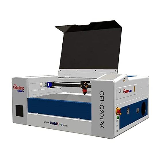
Safety Notice •The users should read the operation manual carefully prior to operating the machine and must obey the operating regulations strictly. • The machine uses IV LASER (strong laser radiation)which type of laser radiation might make following accidents: 1. Easy to burn combustible materials. 2. - Page 5 Appearance of the Machine front: Back View:...
- Page 6 Installation Guide This Highly compact design laser machine is already integrated with a water cooling system as well as an air assist system. The installation is quite easy. You no longer have to prepare a water bucket or install an air pump anymore.
- Page 7 3. Connect the machine to the computer with data cable or Wi-Fi This machine comes with a USB data cable, in which you are able to connect to a laptop. If a Wi-Fi connec- tion is preferred, connect the machine into the Wi-Fi interface and connect the machine to the network. 4.
- Page 8 5. Turn On the machine. Rotate the Control Switch clockwise and the button will bounce up and the machine will be powered on. The laser head starts to move back to its origin point. *For first time installation, when the machine turns on, please do not operate the machine immediately. Wait a few minutes to let the water cooling system fill the laser tube with water fully.
- Page 9 • ABS (acrylonitrile butadiene styrene) • Acrylic (also known as Plexiglas, Lucite, PMMA) • Delrin (POM, acetyl) • High density polyethylene (HDPE)-melts badly • Kempton tape(Polyimide) • Mylar (polyester) • Nylon-melts badly • PETG (polyethylene terephthalate glycol) • Polyethylene (PE)-melts badly •...
-
Page 10: The Control Panel
The Control Panel Introduction to the Keys Reset: Resets the whole system; Origin: Sets the relative origin point; Pulse: Pulses the laser Frame: To track by the current file’s frame; File: The management of the memory and U disc files; Speed: Sets the speed of the current running layer, or set the direction keys’... - Page 11 Introduction to the Control Panel Display When the system is powered on, the screen will show as illustrated above Graph Display Area: Displays the whole file’s track, and display the running track. Running parameters: Displays the running file’s file number, speed, max power etc.; Coordinate: Displays the current coordinate of X,Y and Z axes Graph layer parameters: Displays the layers’...
-
Page 12: Max/Min Power Keys
Speed key Push the “Speed” key when the screen is on the main interface, as shown below: Push the “X+/-“ Keys to move the cursor in the numeral area, and push the “Y +/-” keys to change the value, then push the “Enter” key to save the change, push the “Esc” key to exit from the change. Max/Min power keys Push the “Max Power”... -
Page 13: Set The Layer Parameters
Set the layer parameters After selecting a file to preview on the main interface, the user can push the “Enter” key to let the cursor move to the first layer, then the “Y+/-” keys can be pushed to select the intent layer, at that time, the user can push “Enter”... -
Page 14: Axis Reset
Z/U Key The Z/U key can be pressed when the system is in idle or when the work is finished. On pressing this key, it will show some entries in the following interface: Push the “Y+/-” keys to move the green block to select an item, and then push the “Enter” key to display the sub menu. -
Page 15: Manual Set
Manual set+ When the green block is on this item, push the “Enter” key to show as below Push the “Z/U” key to move the green block, and when the green block is on the “Mode” item, push the “X+-“ keys to select the anticipant value, “Continue” or “Manual”. When “Continue” item is selected, then the “Manual”... -
Page 16: Origin Set
Origin set+ When the green block is on this item, push the “Enter” key to show as below: Push “Z/U” key to move the green block to the anticipant item, and when the green block is on “enable” items, push “Enter” key to enable or disable the item, when enabled, the small diamonds is green, and when disabled, the small diamonds is grey. - Page 17 Language The “Language” item helps you to select an appropriate language which is displayed on the panel below: IP Setup When the green block is on this item, push the “Enter” key to show as below: Push “Z/U” key to move the changing item, then push “X+/-” keys and “Y+/-” keys to change the value, when all the IP value and the Gateway value are changed, push “Enter”...
-
Page 18: Screen Origin
Diagnosis If the “Diagnoses” item is pressed, the system will show as below: This interface shows some system input information, such as limiter status, the status of water protection, the status of the foot switch, etc. When the inputis validated, the color frame will be green, otherwise it’ll be gray. Screen Origin If the “Screen Origin”... - Page 19 File Key Memory File On the main interface, if “File” key is pressed, it will show as below: Read mem file: read the memory file list; Udisk: read the U disk file list; Other: the other operation of the memory files; Run: To run the selected file;...
- Page 20 Current work time: To forecast the running time of the current file (the current file No. is showed on the main interface), and the time is accurate to 1ms. Clear all count: To clear the running times of every file in the memory Delete all file: To delete all memory files Format speedily: To format memory speedily, and then all the files in memory...
- Page 21 Alignment Standards of Optical Path During common use, some deviation may appear with the optical path, resulting in no laser or light path. If so, then please refer to the following method to adjust the optical path: Step 1: First to ensure laser beam from laser tube to the center of the first mirror (#1). Step 2: Add a piece of tape onto the fixture of the mirror in order to mark where the beam is pulsing, press pulse and adjust the mirror accordingly to the center of the beam (with special attention: In order to pre- vent the laser radiation wounding, with a piece of cardboard first to test the approximate location of the...
- Page 22 Step 3: Repeat step 2 for the third mirror Step 4: If the two spots are not superposition, adjust the screws on the back of the 1#mirror to make the laser fire on the same position as the first spot. Step 5: Repeat the second to the fourth steps until the two spots overlap completely.
- Page 23 Step 6: Affix multi-storey double sticky tape paper on the 3# reflector ,move laser head to the nearest position from 2# mirror, press pulse(choose suitable power),get a spot on the paper. Step 7: Move away the laser head to the position farthest from the 2# mirror, press pulse(first to detect the approximate location of laser with a piece of cardboard to prevent wounding),get another spot.
- Page 24 Step 8: If the two spots are not superposition, adjust the screws on the back of the 2# mirror to make the laser fire on the same position as the first spot. Step 9: Repeat the sixth to eighth steps until the two spots overlap completely. Moreover, the spots should be in the center of the hole.
- Page 25 Focus the laser Focusing the laser must be re-done every time a new thickness material is placed on the working platform. The laser uses highly concentrated energy to do its job. Therefore focusing is very important. The distance from the work piece to the laser head normally won’t exceed 20mm. To focus the laser, you have to keep in mind one rule;...
-
Page 26: Lens Replacement
Important: Always be careful when focusing thick material, not to allow material to collide with the lens housing. This can cause serious damage to the laser machine. Lens Replacement Lenses are one of the few parts of a laser machine that need regular maintenance, primarily regular clean- ing. -
Page 27: Maintenance Schedule
problem for new users of any laser machine. Make sure to clean it often, especially if cutting on a regular basis. Lenses that are kept clean last longer. Rotary Attachment Device Installation: The CFL-Q2012K has the option of installing a rotary Attachment. Please consult the Anexo Rotary Tool Installation guide for further information on how to install. -
Page 28: Linear Bearings
Mirror #3 (in the laser head): This mirror is located directly above the focal lens. This mirror should be cleaned at least once a month. If there is any incident of fire or large issue of smoke/fumes, then it is advised to check the mirror and clean it. It is possible to clean the mirror in its mounting bracket, but highly advised to remove the mirror from posi- tion and thoroughly clean it. - Page 29 1) Remove the grease fitting 2) Apply the grease to your finger 3) Push the grease into the little hole 4) push more grease into the little hole, 5) go to step #2 6) Put the grease fitting back on. Rubber belts: The rubber belts should be checked for appropriate tension at least every six months.
- Page 30 Storage of the laser: Store the laser in a clean, dry, warm location with no vibrations.
- Page 31 Use a dehumidifier: Humidity can cause the metal parts of the laser machine to rust. All metal is expected to rust. One unex- pected metal surface is the laser mirrors. It is best to try to control the humidity level in the laser work area. Clean the mirrors and check for this oxidation as a possible problem.
- Page 32 TECH SUPPORT: support.us@camfive.com SALES: sales.us@camfive.com CALIFORNIA 626-855-4515 219 S. 3rd Ave Suite 3, Los Angeles, CA 91746 Florida 407-851-5525 1629 Prime Ct Suite 700, Orlando, FL 32809...
Need help?
Do you have a question about the Qustom Laser CFL-Q2012K and is the answer not in the manual?
Questions and answers