Table of Contents
Advertisement
Quick Links
IN STAL LA TION IN STRUC TIONS FOR EN ERGY RE COV ERY SYS TEMS (ERS)
SHIP PING AND PACK ING LIST
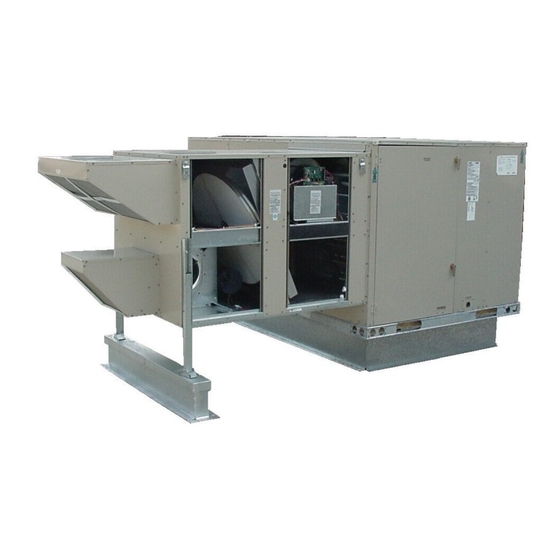
Package 1 of 1 contains: See Illustration 1 and 2.
1 - Energy Recovery System Assembly
1 - Outdoor Fresh Air Hood with Filter
1 - Outdoor Exhaust Air Hood with Barometric
Damper
1 - Top Filler Panel
1 - Bottom Filler Panel w/ Platform Support Rail
(Mounted)
2 - Side Filler (Installed on ERS)
1 - Hardware Bag:
14' - Gasket ¾" x 1 ¼"
1
7' - Gasket
" x ½"
8
1 - Field Harness
4 - Wire Ties
10 - Self-Tapping Screws 10-16 x ½"
8 - Gold Screws 10-16 x ½"
1 - Installation Instruction
PRIN CI PLE OF OPERATION
The ERS enthalpy wheel contains parallel layers of a
polymeric material that are impregnated with silica gel
(desiccant). The wheel is located in the entering (intake)
air and exhaust air streams of the ventilation equipment.
As the wheel rotates through each air stream, the wheel
surface adsorbs sensible and latent energy. In the heating
mode, the wheel rotates to provide a constant transfer of
heat from the exhaust air stream to the colder intake air
stream. During the cooling season, the process is
reversed. When the temperatures are mild the wheel
pivots out of the air stream to allow economizer to operate
FIL TER ACCESS
EN ERGY
RE COV ERY
FRESH
CON TROL BOARD
AIR
EX HAUST FAN
EXHAUST
POWER EN TRY
AIR
20
5
16
KITS AND ACCESSORIES
P20A-50LDW
July 12, 2010
Supersedes 02-12-10
USED WITH LC/LG 072 SE RIES UNITS
Patent# 5,548,970
ETL Certified
per UL 1995
and CSA 22.2
FRESH AIR BLOWER
WHEEL
WIR ING
MAKEUP
BOX
55
3
8
EN ERGY RE COV ERY SYSTEM
normally for "free cooling" when outdoor temperature and
humidity is acceptable. During economizer operation, the
ERS exhaust blower continues to run, providing power
exhaust for the system. The intake blower is de-energized
during economizer operation.
Improper installation, adjustment, alteration, service
or maintenance can cause property damage,
personal injury or loss of life. Installation and servi ce
must be performed by a qualified installer or service
agency.
20
5
16
OUT DOOR AIR DAMPERS
MIXED AIR
RETURN AIR
PAGE 1
50P2050xH
WARNING
37 ¼
3
55
8
TELE SCOP IN G LEG
Illustration 1
37 ¼
MIXED AIR
OUTDOOR AIR
RETURN/
EXHAUST AIR
Illustration 2
37 ½
37 ½
Advertisement
Table of Contents

Summary of Contents for Lennox 50P2050 H Series
- Page 1 KITS AND ACCESSORIES 50P2050xH P20A-50LDW EN ERGY RE COV ERY SYSTEM July 12, 2010 Supersedes 02-12-10 IN STAL LA TION IN STRUC TIONS FOR EN ERGY RE COV ERY SYS TEMS (ERS) USED WITH LC/LG 072 SE RIES UNITS Patent# 5,548,970 normally for "free cooling"...
-
Page 2: Shipping Damage
4. If a factory install ERS Harness (J298/P153) is CAUTION installed go to Step 5, otherwise use the provided harness from the hardware bag within the ERS and complete the following steps. Electric shock hazard. Can cause in jury or death. Before attempting to perform A. - Page 3 E. Route wire through the control section down to the IMC2 control board. Strip the wire ends 3/8" if they have not been pre-done. Place the Green wire under screw terminal at J298-8 (Purple connector). Do the same routine for Pink at J298-10 and Black to J298-9.
- Page 4 9. Use provided 10-16 x ½" self-tapping screws to secure 2. Attach bottom filler panel with platform support rail to the of the ERS to the rooftop unit. See Figure 12. bottom opening of rooftop unit aligning with screw holes used by removed door panel. Secure in place as shown in Figure 10 TOP FILLER PANEL SIDE MOUNT ING FLANGE...
- Page 5 2. The minimum damper blade position must be adjusted on the economizer control board to the correct amount of outside air specified by the customer. Refer to Lennox rooftop unit manual for setting. Wheel Pivot Adjustment Figure 17 The Electronic Configuration To Order (ECTO) parameter must be set at ECTO 7.22 = 10 to indicate...
-
Page 6: Econo Mizer Set Tings
D02 (turns on B29 thru ERS controller) are relay outputs above minimum air flow for fresh air requirements at the customers specified conditions. from Lennox IMC2 control board. BLOWER SPEED AD JUST MENT B28 - ERS Wheel Motor, B26 - ERS Exhaust Air Blower,... -
Page 7: Maintenance
6. Disconnect main power to unit before making adjustment to economizer and/or ERS unit. 7. Remove all jumpers and replace ERS control access cover. DELTA PRES SURE 8. Set thermostat to normal operating position. FRESH AIR 9. Restore power to unit. MAINTENANCE Motor Maintenance All motors use prelubricated sealed bearings;... - Page 8 PAGE 8...
- Page 9 PAGE 9...
- Page 10 PAGE 10...
- Page 11 CFM Range Volt age Phase 50P2050xH23 14" 1000-1700 208- 230 50P2050xH33 14" 1000-1700 50P2050xH43 14" 1000-1700 ERS Lay out Clear ance 24" 012104808 Lennox Unit Outline Equipment Support 50P2050xH 48.000 502014414 Roof Curb 58.208 2.093 Clear ance 42" PAGE 11...
-
Page 12: Installation Checklist
START UP INFORMATION SHEET VOLTAGE - ERS UNIT In com ing Volt age L1-L2 L1-L3 L2-L3 Run ning Volt age L1-L2 L 1-L3 L2-L3 Sec ond ary Volt age C (black) to G (green) Volts* C (black) to W (white) Volts* * With ther mo stat call ing.
Need help?
Do you have a question about the 50P2050 H Series and is the answer not in the manual?
Questions and answers