
Summary of Contents for VERSATEK VX-MD4024
- Page 1 VX-MD4024 IP Digital Subscriber Line Access Multiplexer HW Installation and User Guide Part Number A0-31-0129-2.1 , April 2010 Issue 2.1 Draft...
-
Page 3: Mandatory Regulations
International Electrotechnical Commission General Requirements The sections that follow outline the mandatory regulations that govern the installation and operation of the VX-MD4024 . You must adhere to these instructions so that your system meets regulatory requirements. Prevention of Access The VX-MD4024 must be accessible only to authorized personnel. Install this apparatus in a restricted access location or similar environment to prevent unauthorized access. - Page 4 Mandatory Regulations Regulations compliance Safety Approval The system complies with the following safety norms: – Product Safety Requirements identified in EN60950:2000 – Over Voltage Protection Requirements of ITU-T K.20 EMI/EMC The system meets the requirements of Telecommunications Network Equipment: EN300-386. Electromagnetic Compliance The system complies with the standard FCC Part 15 Class A and EN55022.
-
Page 5: Table Of Contents
Housekeeping and Alarm Contact Output Interface ............15 Provisioning a Management IP port................17 Configuration Import/Export ..................21 Firmware Update ....................... 23 — Operating and Maintaining the VX-MD4024 ........... 25 Maintenance requirement ..................26 2.1.1 Tools and Equipment Requirements ................26 2.1.2... - Page 6 Replacing Units ......................31 — Troubleshooting the VX-MD4024 ..............32 Introduction to Troubleshooting ................33 Resolving Problems Indicated Through LEDs ............33 Resolving Problems Indicated Through Alarms ............34 Procedures for Troubleshooting the VX-MD4024 ........... 34 Abbreviations ........................38 Abbreviations...
-
Page 7: List Of Figures
Figure 1-1 Console Setting ........................... 5 Figure 1-2 Mounting Bracket Orientation (Top View) ................... 6 Figure 1-3 Mounting Bracket Position for Standard Mount (VX-MD4024 -DC shown) ........ 7 Figure 1-4 Power connection and power switch of VX-MD4024 ..............8 Figure 1-5 VX-MD4024 grounding screw on the front panel............... 9 Figure 1-6 Pin Assignment of LINE Interface (VDSL2 30a, Horizontal Tip/Ring model) ...... - Page 8 Procedures of Powering Up the DSLAM .................. 28 Table 2-3 Procedures of Powering Down the DSLAM ................28 Table 2-4 VX-MD4024 Controls and LED Indication ................29 Table 3-1 Problems Indicated by LEDs ...................... 33 Table 3-2 List of Troubleshooting Procedures ................... 34...
-
Page 9: Preface
For information about how to manage the DSLAM through Command Line Interface (CLI) commands, refer to the VX-MD4024 CLI Command Reference. For information about how to manage the DSLAM through Web GUI, refer to the VX-MD4024 Web Configuration Tool Guide. -
Page 10: Installation Of The Vx-Md4024
3 Installation of the VX-MD4024 — Installation of the VX-MD4024 1.1 Pre-Installation 1.2 Hardware Installation 1.3 Provisioning a Management IP Port 1.4 Configuration Import/Export 1.5 Firmware Update 2 / 44... -
Page 11: Pre-Installation
The information includes required installation tools, safety requirements, and electrostatic discharge protection. 1.1.1 Tools and Test Equipment Requirements To install and maintain the VX-MD4024, you should have the tools and test equipment listed in the Table 1-1. Table 1-1 Required Installation Tools and Materials... -
Page 12: Hardware Installation
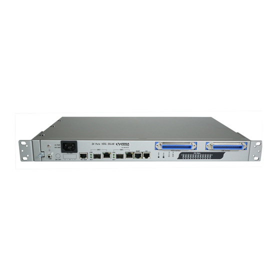
Please perform the procedures in the suggested order. 1.2.1 Hardware Type There are a total of 4 different types of VX-MD4024 hardware with the front panel view. Figure 1-1 VX-MD4024 with DC power and no splitter Figure 1-2 VX-MD4024 with DC power and splitter... -
Page 13: Factory Default Management Ip Addresses
1 — Installation of the VX-MD4024 1.2.2 Factory Default Management IP Addresses Management Out-of-band IP-Address, Subnet Mask ⚫ 192.168.1.1, 255.255.255.0 Management Out-of-band Default Gateway ⚫ 192.168.1.254 Management In-band IP-Address, Subnet Mask ⚫ 192.168.5.3, 255.255.255.0 1.2.3 Installation Overview The installation consists of the following procedures. Each procedure will be explained in detail in... -
Page 14: Mounting The Vx-Md4024
1 — Installation of the VX-MD4024 1.2.4 Mounting the VX-MD4024 The position and orientation of the brackets depends on the rack used for mounting. The DSLAM can be front-mounted in a standard channel rack (5-inch projection); and it can be shipped with the mounting brackets installed in one of three mounting positions or shipped loose (see Figure 1-6). - Page 15 1 — Installation of the VX-MD4024 For 23’’ Rack For 19’’ Rack Figure 1-7 Mounting Bracket Position for Standard Mount (VX-MD4024 -DC shown) 7 / 44...
-
Page 16: Power And Ground Connections
Figure 1-8 Power connection and power switch of VX-MD4024 AC Power Connection If your VX-MD4024 uses AC power, connect the AC power cord to the AC supply socket on the front panel of the DSLAM (refer to Figure 1-8), and plug the cord into the external power source. - Page 17 -48VDC power supplier of telecom equipment. This is to guarantee our products against interferences by other equipment while they are working. Ground Connections This section provides the grounding rule for the VX-MD4024 . All remote system sites must be properly grounded for optimum system performance. In Central Office: There should be a CO GND that is adequately grounded.
-
Page 18: Connecting The Vdsl/Adslx And Pots Interfaces
1 — Installation of the VX-MD4024 1.2.6 Connecting the VDSL/ADSLx and POTS interfaces The VX-MD4024 supports 24 ports VDSL2/ADSLx subscribers per box. Depending on your box, there maybe two RJ21 50-pin female connectors on the front panel of the system. One for VDSL/ADSLx line and the other for POTS interface. - Page 19 1 — Installation of the VX-MD4024 POTS port 1~24: Pin No. Port No. Pin No. Ring Ring Ring Ring Ring Ring Ring Ring Ring Ring Ring Ring Ring Ring Ring Port No. Figure 1-12 Pin Assignment of POTS Interface 11 / 44...
-
Page 20: Connecting The Gbe1/Gbe2 Trunk Interface
1 — Installation of the VX-MD4024 1.2.7 Connecting the GBE1/GBE2 trunk interface The system provides two types of trunk interfaces (two ports for each type): electrical (RJ-45) and optical (mini-GBIC) interfaces. When both electrical and optical ports are connected, system will automatically select the interface according to the priority setting (Fiber first or Copper first). -
Page 21: Ethernet Port (Mgmt)
1 — Installation of the VX-MD4024 1.2.8 Ethernet Port (MGMT) The VX-MD4024 provides one RJ45 Jack (MGMT) on the front panel for Ethernet interface connection. The detailed pin assignment is shown in the following figure and table. Other pins Bob Smith... -
Page 22: Console Port (Cid)
1 — Installation of the VX-MD4024 1.2.9 Console Port (CID) The Console interface (CID) on the front panel is the main control interface of the VX-MD4024 . The RJ45 connector pin assignment is illustrated below: Other pins unused Figure 1-15 Console Port RJ-45 pin assignment To connect the host PC to the console port, a RJ45 (male) connector-to-RS232 DB9 (female) connector cable is required. -
Page 23: Housekeeping And Alarm Contact Output Interface
1 — Installation of the VX-MD4024 1.2.10 Housekeeping and Alarm Contact Output Interface The VX-MD4024 has an RJ-50 port (HK) on the front panel to provide four housekeeping inputs and one alarm contact output. Generally, housekeeping contacts can connect to environment- sensor- controlled switch to indicate the operation environment condition. - Page 24 1 — Installation of the VX-MD4024 Environment UMAP2200 Sensor 3.3 Vdc HK_IN HK_COM UMAP2200 ALMOUT Alarm Equipment ALMCOM Figure 1-18 Operation diagram of Housekeeping Inputs and Alarm Contact Output Note — The maximum current and voltage for ALMOUT / ALMCOM is restricted to 0.5 A 30 VDC or 0.15 A 125 VAC (resistive load).
-
Page 25: Provisioning A Management Ip Port
1 — Installation of the VX-MD4024 Provisioning a Management IP port This section describes how to use CLI commands or Web GUI to provision an IP port for the VX- MD4024. Referring to the previous section, use a console cable to connect a host PC and the VX- MD4024 through its console port (COM). - Page 26 /*Save new setting to memory*/ After setting the in-band/out-band IP of the VX-MD4024 , remember to connect its Ethernet port MGMT to the Ethernet LAN. Then in the previous PC terminal screen, type the following command to verify if the Ethernet connection between the management station and the DSLAM is working.
- Page 27 = 1.0/1.1/1.6 ms localhost:% Now you can access the VX-MD4024 via Telnet on port 23 (for using CLI) or Web GUI by entering its IP address in your browser’s URL/address field. Besides CLI, you can also change the in-band/out-band management IP of the VX-MD4024 in the Web GUI: a.
- Page 28 1 — Installation of the VX-MD4024 will save inband configuration and runtime configuration as the active restoration database for next power-on restoration. You shall wait for memory write success message. 20 / 44...
-
Page 29: Configuration Import/Export
1 — Installation of the VX-MD4024 Configuration Import/Export The configuration database of VX-MD4024 contains two kinds of database - inband database and general database. Inband database contains configuration for the inband channel and is shared by two boot images (no matter which boot point you choose, the inband configuration keeps the same). - Page 30 [noreboot] /*You must add the word “noreboot” for action (L) so that the system will not reboot automatically once the DB is imported*/ In Web: Please refer to VX-MD4024 Web Configuration Tool Guide. 22 / 44...
-
Page 31: Firmware Update
2. Prepare an FTP server and make sure the needed files are put in it. 3. Make sure that the connection between VX-MD4024 and the FTP server is fine. You can use ‘ping <ip address>’ command to ping the FTP server from CLI, or you can ping the VX- MD4024 from the FTP server. - Page 32 MUST NOT turn off or reset the system. 4. After system restarts, login the CLI again and use the ‘show firmware partition’ or ‘show bootloader’ command to check if the software upgrade is successful. In Web: Please refer to VX-MD4024 Web Configuration Tool Guide. 24 / 44...
-
Page 33: Operating And Maintaining The Vx-Md4024
— Operating and Maintaining the VX-MD4024 2.1 Maintenance Requirement 2.2 Powering the DSLAM Up or Down 2.3 Controls and LED Indication 2.4 Replacing Units 25 / 44... -
Page 34: Maintenance Requirement
2 — Operating and Maintaining the VX-MD4024 Maintenance requirement 2.1.1 Tools and Equipment Requirements Table 2-1 lists required tools and test equipment for the VX-MD4024 system maintenance. Table 2-1 Required Installation Tools and Materials Item Required Purpose Anti-static wrist strap... -
Page 35: Electrostatic Discharge Protection
SNMP. It allows user to view the current system status, alarm information and to take the necessary corrective action if a problem is reported. Also keep each VX-MD4024 system site free of dust and other pollutant that could affect system performance. In addition, be sure to maintain the environment conditions at the central office and ... -
Page 36: Powering The Vx-Md4024
2 — Operating and Maintaining the VX-MD4024 Powering the VX-MD4024 Up or Down This section describes how to power up the DSLAM and how to power down the DSLAM. Table 2-2 Procedures of Powering Up the DSLAM Step Action Put on the antistatic wrist strap and connect it to a grounding point. -
Page 37: Controls And Led Indication
2 — Operating and Maintaining the VX-MD4024 Controls and LED Indication The VX-MD4024 has simple controls and indicators on its front panel. The indicators show the current operating states of various system elements and serve as maintenance aids for local technicians at each site. - Page 38 2 — Operating and Maintaining the RU Amber At power on phase Self-test fail Green Normal Operation Green - Blink Remote download in operation At power on phase Major alarm set Red – Blink Major and Minor alarm set Amber Minor alarm set Green Normal operation...
-
Page 39: Replacing Units
2 — Operating and Maintaining the RU Replacing Units This section provides procedures on how to: replace the air filter (replace every three months) Air Filter Panel Procedure 2-1 Replace the Air Filter Note — You must loosen the connection of the Air Filter Panel to the DSLAM and pull out the Air Filter before replacing the air filter. -
Page 40: Troubleshooting The Vx-Md4024
— Troubleshooting the VX-MD4024 3.1 Introduction to Troubleshooting 3.2 Resolving Problems Indicated Through LEDs 3.3 Resolving Problems Indicated Through Alarms 3.4 Procedures for Troubleshooting the VX-MD4024 32 / 44... -
Page 41: Introduction To Troubleshooting
Introduction to Troubleshooting This chapter describes instructions for troubleshooting the VX-MD4024. These procedures may require the presence of technicians at remote VX-MD4024 system sites and an additional operator at PC to monitor system alarms by console or EMS during maintenance. -
Page 42: Resolving Problems Indicated Through Alarms
3 — Troubleshooting the VX-MD4024 Resolving Problems Indicated Through Alarms Alarms of the system are viewed through CLI commands, Web GUI or EMS. If an alarm indicates a problem, refer to section 3.4 for troubleshooting procedures. Procedures for Troubleshooting the VX-MD4024 When you follow a troubleshooting procedure, start from the first step of the procedure. - Page 43 3 — Troubleshooting the VX-MD4024 Procedure 3-1 Troubleshoot VX-MD4024 Power Up Problems Problem indication: • The SYS LED on the front panel is not lit even though the DSLAM is powered up • Alarm that indicates a system power up problem •...
- Page 44 3 — Troubleshooting the VX-MD4024 Procedure 3-3 Troubleshoot VDSL/ADSLx Service Problems Problem indication: No VDSL/ADSLx service to the affected subscribers (POTS service is ok). 1 If all subscribers connected to the DSLAM are affected, and the SYS LED on the front panel is not lit, check the power source.
- Page 45 3 — Troubleshooting the VX-MD4024 Procedure 3-5 Subscriber Service Problems Problem indication: No POTS and VDSL/ADSLx service to the affected subscribers. 1 Check the connection of the subscriber lines and POTS lines at the subscriber line connector for DSLAM for subscribers that do not have POTS and VDSL/ADSLx service.
-
Page 46: Abbreviations
Abbreviations ADSL asymmetrical digital subscriber line ADSLx ADSL/ADSL2/ADSL2+ ANSI American National Standards Institute asynchronous transfer mode command line interface DSLAM digital subscriber line access multiplexer element management system digital subscriber line electromagnetic compatibility electromagnetic immunity ETSI European Telecommunications Standards Institute Mbps megabit per second main distribution frame... - Page 47 39 / 44...
Need help?
Do you have a question about the VX-MD4024 and is the answer not in the manual?
Questions and answers