Table of Contents
Advertisement
Quick Links
Service Manual
Specifications:
Power Source:
Power Requirements:
Output: (IEC705-88)
Microwave Frequency:
Timer:
Oven Cavity Size:
Outside Dimensions:
Inside Dimensions:
Weight:
Inverter Power Supply
Output power:
240 V AC Single Phase, 50 Hz
Microwave: 1100W, Grill: 1210W, Maximum: 1890W
900W
2,450Mhz
99 min. 99 sec.
20L
458mm (W) X 315mm (D) X 299mm (H)
315mm (W) X 298mm (D) X 208mm (H)
12 Kg
IEC705-88 Test procedure
Specifications subject to change without notice
ORDER NO. MOP9905001C2
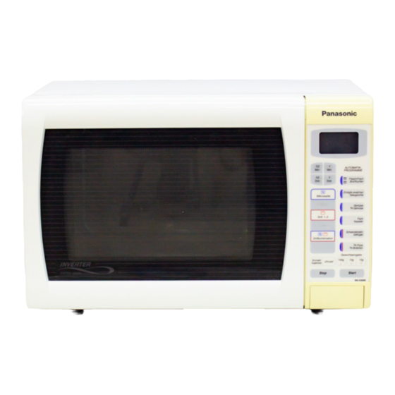
Microwave Oven
NN-V359WB
© 1999 Matsushita Electric Industrial Co., Ltd.
All rights reserved. Unauthorized copying and
distribution is a violation of law.
Advertisement
Table of Contents
Troubleshooting

Subscribe to Our Youtube Channel
Related Manuals for Panasonic NN-V359WB


Summary of Contents for Panasonic NN-V359WB
- Page 1 ORDER NO. MOP9905001C2 Service Manual Microwave Oven NN-V359WB Specifications: Power Source: 240 V AC Single Phase, 50 Hz Power Requirements: Microwave: 1100W, Grill: 1210W, Maximum: 1890W Output: (IEC705-88) 900W Microwave Frequency: 2,450Mhz Timer: 99 min. 99 sec. Oven Cavity Size:...
- Page 2 WARNING This service information is designed for experienced repair technicians only and is not designed for use by the general public. It does not contain warnings or cautions to advise non-technical individuals of potential dangers in attempting to service a product. Products powered by electricity should be serviced or repaired only by experienced professional technicians.
-
Page 3: Table Of Contents
TABLE OF CONTENTS CONTROL PANELS .................................. 4 OPERATION AND DIGITAL PROGRAMMER CIRCUIT TEST PROCEDURE ................ 5 SCHEMATIC DIAGRAM................................8 DESCRIPTION OF OPERATING SEQUENCE ......................... 9 Variable power cooking control ............................9 Grill cooking..................................9 Combination cooking................................. 9 Autoweight defrost, autoweight cook..........................9 CAUTIONS TO BE OBSERVED WHEN TROUBLESHOOTING.................... -
Page 4: Control Panels
CONTROL PANELS Display Window Time Pads Auto Weight Combination Programs Auto Weight Defrost Programs Microwave Power Settings Grill Settings Combination Pad Delay/Stand Pad: This can be used to delay a cooking program for up to 9 hrs 99 mins., or used to time or for standing (non-cooking) time. -
Page 5: Operation And Digital Programmer Circuit Test Procedure
OPERATION AND DIGITAL PROGRAMMER CIRCUIT TEST PROCEDURE Operation guide on the display. To assist in programming, the next operation will appear on the display. When you are used to operating the oven, you can turn the operating guide off. To turn off: To turn on: Press 3 times Press 3 times... - Page 6 4. DELAY STAND 7. COMBINATION COOKING OPERATION DISPLAY OPERATION DISPLAY 1. Set power level and time 1. Press combination COMBINATION SELECT GRILL LEVEL 2. Press stand STAND Delay/ SET TIME Stand 2. Press stand GRILL 1 3. Set standing time 1.
- Page 7 9. TO SET CHILD SAFETY LOCK OPERATION DISPLAY 1. Press start 3 times to display lock * LOCK 10. TO RESET CHILD LOCK OPERATION DISPLAY 1. Press stop/cancel 3 times Time of day or colon appears in display 11:25 11. DEMONSTRATION MODE OPERATION DISPLAY 1.
-
Page 8: Schematic Diagram
SCHEMATIC DIAGRAM W IR IN G D IA G R A M N O TE : *W he n rep lacing, check the lead colour as sho w n. *C olours show n by ( ) in dicate colours of le adw ire con nector ho using. M AG N ETRO N C A U TIO N : H E AT S IN K... -
Page 9: Description Of Operating Sequence
DESCRIPTION OF OPERATING SEQUENCE 4.1 Variable power cooking control VARIABLE POWER COOKING POWER OUTPUT RY-1 INVERTER HIGH VOLTAGE INVERTER POWER SUPPLY (U) controls SETTING POWER CONTROL output power by a signal from Digital Programmer Circuit (DPC). APPROX. SIGNAL Power relay 1 stays on to supply power to the inverter circuit. HIGH 900W stay ON... -
Page 10: Cautions To Be Observed When Troubleshooting
CAUTIONS TO BE OBSERVED WHEN TROUBLESHOOTING Unlike many other appliances, the microwave oven is high- voltage, high-current equipment. Though it is free from danger in ordinary use, extreme care should be taken during repair. H.V. INVERTER(U) CAUTION Servicemen should remove their watches whenever working BE SURE TO HAVE PROPER close to or replacing the magnetron. -
Page 11: When Parts Must Be Replaced, Remove The Power Plug From The Outlet
5.3 When parts must be replaced, remove 5.6 Confirm after repair the power plug from the outlet. 1. After repair or replacement of parts, make sure that the screws of the oven, etc. are neither loose nor missing. 5.4 When the 10A fuse is blown due to the Microwaves might leak if screws are not properly tightened. -
Page 12: Disassembly And Parts Replacement Procedure
DISASSEMBLY AND PARTS REPLACEMENT PROCEDURE 6.1 Magnetron DANGER 1. Discharge the high voltage capacitors. HIGH VOLTAGE 2. Disconnect wire terminals to the thermal cutout. AREA 3. Remove 1 screw holding the thermal cutout bracket to the magnetron. AIR GUIDE 4. Remove 1 screw holding the air guide A. 5. -
Page 13: Digital Programmer Circuit (Dpc) And Membrane Key Board
6.3 Digital Programmer Circuit (DPC) and 6.5 Fan Motor membrane key board. 1. Remove 2 screws and remove tie bar. 2. Disconnect 2 lead wires from fan motor terminals. NOTE: Be sure to ground any static electric charge built up on 3. -
Page 14: Door Disassembly
6.7 Door disassembly 1. Remove door C from door E by carefully pulling outward starting from upper right hand corner using a flat blade TURNTABLE MOTOR screwdriver. 2. Remove 4 screws holding door E to door A assembly to separate door E from door A. 3. -
Page 15: Component Test Procedure
COMPONENT TEST PROCEDURE 7.3 Magnetron Continuity checks can only indicate an open filament or a CAUTION NEW H.V. shorted magnetron. To diagnose for an open filament or shorted 1. High voltage is present at the high voltage terminal of the magnetron. -
Page 16: Inverter Power Supply (U)
7.5 Inverter Power Supply (U) DO NOT try to REPAIR this H.V. Inverter power supply(U). Replace as whole H.V. Inverter(U) Unit. HIGH VOLTAGE HEAT SINK TRANSFORMER (RECTIFIER BRIDGE) CHOKE COIL FILM CAPACITORS CN 702 SAND BAR RESISTOR PRIMARY WINDINGS CUSTOM I.C. HIGH VOLTAGE DIODES PHOTO COUPLER CN 701... -
Page 17: Measurements And Adjustments
MEASUREMENTS AND ADJUSTMENTS WARNING • For continued protection against radiation hazard, replace only with identical replacement parts. • When the 10 Amp. fuse is blown due to the operation of SCREW short switch, you must replace Primary latch switch and short switch. -
Page 18: Troubleshooting Guide
TROUBLESHOOTING GUIDE NEW H.V. CAUTION 1. DO NOT try to REPAIR this H.V. Inverter power supply(U). Replace as whole H.V. Inverter(U) Unit. When returning H.V. Inverter(U) make sure to pack as originally packed. 2. DO NOT RE-ADJUST PRESET VOLUME on the H.V. Inverter(U). It is very dangerous to repair or adjust without sufficient test equipment because this circuit handles very large current with very high voltage. - Page 19 SYMPTOMS CAUSE CORRECTIONS 10 Turntable motor does not rotate. 1. Open or loose wiring of turntable motor 2. Defective turntable motor 11 Oven stops operation during cooking. 1. Open or loose wiring of primary and Adjust door and latch switches. secondary latch switch 2.
- Page 20 NEW H.V. Alternative way to troubleshooting oven with AC Ampare meter used. Oven shuts down after approximately 15 or 33 seconds. If the microwave oven shuts down after a short time in micropower mode, conduct the following test. The microwave oven must be set in test mode to activate the self diagnostic failure code system. SELF TEST MODE DISPLAY DELAY/...
- Page 21 Trouble Related to Digital Programmer Circuit SYMPTOM STEP CHECK RESULT CAUSE/CORRECTIONS No display when oven is first Fuse pattern of DPC Normal STEP 2 plugged in. Open (NOTE) Shorted Circuit of ZNR, L.V.T., Oven Lamp etc. Replace DPC IC10 Pin 9 Abnormal 0V IC10 Oven is dead.
-
Page 23: Parts Lists
11. PARTS LISTS NOTES: *When ordering replacement part(s), please use part number(s) shown in this parts list. Do not use description of the part. *Important safety notice: Components identified by ! mark have special characteristics important for safety. When replacing any of these components, use only manufacturer’s specified parts. -
Page 24: Door Assembly
12. DOOR ASSEMBLY Ref. No. Part No. Part Name & Description Pcs/Set Remarks E302A4L20HBP DOOR A SCREEN B ASSEMBLY E30214000AP DOOR KEY SPRING E30184L00GS DOOR KEY A E302K4L00GS DOOR E AND SCREEN A UNIT E31454L00GS SCREEN A E30854L00GS DOOR C E30064L00GS UPPER HINGE NOTE: When ordering any door component also order door C as this part may become damaged during disassembly. -
Page 25: Escutcheon Base Assembly
13. ESCUTCHEON BASE ASSEMBLY Ref. No. Part No. Part Name & Description Pcs/Set Remarks E80724L10HBP DOOR OPENING BUTTON E80378AOAG DOOR BUTTON SPRING E80344L10HBP ESCUTCHEON BASE E81274L10BP ESCUTCHEON BACK PLATE E603L4L20BP DPC AU E66164L00GS RIBBON CABLE E82564L10BP DOOR OPENING LEVER E603Y4L20BP DPC DU E83264L10BP DISPLAY SHEET... -
Page 26: Packing And Accessories
14. PACKING AND ACCESSORIES Ref. No. Part No. Part Name & Description Pcs/Set Remarks E060V4L20BP WIRE RACK ASSEMBLY E06435870GS WIRE RACK FOOT E290D6150WN ROLLER RING E06014L00BP GLASS TRAY E00034L20BP INSTRUCTION BOOK E01695750BP SERVICE CENTER LIST E01084L00GS TRAY PACKING E01054L00BP LOWER FILLER E01024L20HBP CARTON BOX E01074L00GS... - Page 27 E607X4L00BP - Noise Filter Assembly Ref. No. Part No. Description Remarks ERG1SJ753P RESISTOR 75KΩ 1W C1&C2 AECQJ5225KX1 CAPACITOR 2.2µf C3&C4 ECKMNA472ME CAPACITOR 4700pF 250V AC E621A4J00XN FILTER COIL 2.4mH E03594080BP EARTH WIRE E62316010BP FUSE HOLDER 10A 250V AC...
-
Page 28: Digital Programmer Circuit
15. DIGITAL PROGRAMMER CIRCUIT... -
Page 30: Digital Programmer Circuit - Parts List
16. DIGITAL PROGRAMMER CIRCUIT - PARTS LIST DPC AU - E603L4L20BP Ref. No. Part No. Description Remarks AEEM19FESVKN 19PIN CONNECTOR DISP110 AEDDHLC4L2BP IC220 AN6747B CUSTOM IC D180-D182 AESQTLGE260T GREEN LED CX320 EF0MC8004T4 CERAMIC RESONATOR SW40-42 EVQ11L05R PUSH SWITCH SW44-48 SW51 SW53-63 R182 ERDS2TJ361T... - Page 31 NOTES:...
- Page 32 NOTES: S - 4L20BP Printed in the UK...
Need help?
Do you have a question about the NN-V359WB and is the answer not in the manual?
Questions and answers