Table of Contents
Advertisement
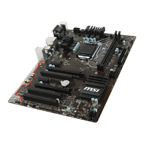
Unpacking
Thank you for buying the MSI
B150-ICAFE/ H110 PC MATE
motherboard. Check
®
to make sure your motherboard box contains the following items. If something is
missing, contact your dealer as soon as possible.
Drivers & Utilities
Motherboard User
Disc
Guide
Motherboard
I/O Shield
SATA Cable
1
Unpacking
Advertisement
Table of Contents

Related Manuals for MSI B150-ICAFE/ H110 PC MATE


Summary of Contents for MSI B150-ICAFE/ H110 PC MATE
-
Page 1: Unpacking
Unpacking Thank you for buying the MSI B150-ICAFE/ H110 PC MATE motherboard. Check ® to make sure your motherboard box contains the following items. If something is missing, contact your dealer as soon as possible. Drivers & Utilities Motherboard User... -
Page 2: Safety Information
Safety Information The components included in this package are prone to damage from electrostatic discharge (ESD). Please adhere to the following instructions to ensure successful computer assembly. Ensure that all components are securely connected. Loose connections may cause the computer to not recognize a component or fail to start. Hold the motherboard by the edges to avoid touching sensitive components. -
Page 3: Quick Start
Quick Start Preparing Tools and Components Intel LGA 1151 CPU ® CPU Fan Thermal Paste DDR4 Memory Power Supply Unit Chassis SATA Hard Disk Drive Graphics Card SATA DVD Drive A Package of Screws Phillips Screwdriver Quick Start... -
Page 4: Installing A Processor
Installing a Processor http://youtu.be/bf5La099urI Quick Start... -
Page 5: Installing Ddr4 Memory
Installing DDR4 memory http://youtu.be/T03aDrJPyQs Quick Start... -
Page 6: Connecting The Front Panel Header
Connecting the Front Panel Header http://youtu.be/DPELIdVNZUI HDD LED + Power LED + HDD LED - Power LED - Reset Switch Power Switch Reset Switch Power Switch JFP1 Reserved No Pin JFP1 HDD LED - HDD LED HDD LED + POWER LED - POWER LED POWER LED + Quick Start... -
Page 7: Installing The Motherboard
Installing the Motherboard Quick Start... -
Page 8: Installing Sata Drives
Installing SATA Drives http://youtu.be/RZsMpqxythc Quick Start... -
Page 9: Installing A Graphics Card
Installing a Graphics Card http://youtu.be/mG0GZpr9w_A Quick Start... -
Page 10: Connecting Peripheral Devices
Connecting Peripheral Devices Quick Start... -
Page 11: Connecting The Power Connectors
Connecting the Power Connectors http://youtu.be/gkDYyR_83I4 JPWR1 JPWR2 Quick Start... -
Page 12: Power On
Power On Quick Start... -
Page 13: Table Of Contents
Contents Unpacking ......................1 Safety Information ....................2 Quick Start ......................3 Preparing Tools and Components ................3 Installing a Processor ..................... 4 Installing DDR4 memory ..................5 Connecting the Front Panel Header ............... 6 Installing the Motherboard ..................7 Installing SATA Drives..................... - Page 14 BIOS Setup ......................34 Entering BIOS Setup ..................... 34 Resetting BIOS ...................... 35 Updating BIOS ....................... 35 System Status Menu ..................... 36 Advanced Menu ..................... 37 Overclocking Menu ....................44 M-Flash Menu ....................... 50 Security Menu ....................... 51 Boot Menu ......................53 Save &...
-
Page 15: Specifications
Supports Intel Extreme Memory Profile (XMP)** ® * Please refer www.msi.com for more information on compatible memory. ** DDR4 2133 MHz and higher memory modules will only run at maximum of DDR4 2133 MHz on XMP mode due to Intel chipset limitation. - Page 16 Continued from previous page B150-ICAFE Intel B150 Chipset ® 6x USB 3.1 Gen1 (SuperSpeed USB) ports (4 ports on the ƒ back panel, 2 ports available through the internal USB connector) 6x USB 2.0 (High-speed USB) ports (2 ports on the ƒ...
- Page 17 Continued from previous page 1x 24-pin ATX main power connector 1x 8-pin ATX 12V power connector 6x SATA 6Gb/s connectors (B150-ICAFE) 4x SATA 6Gb/s connectors (H110 PC MATE) 2x USB 2.0 connectors (supports additional 4 USB 2.0 ports) (B150-ICAFE) 1x USB 2.0 connector (supports additional 2 USB 2.0 ports) (H110 PC MATE) 1x USB 3.1 Gen1 connector (supports additional 2 USB 3.1 Gen1 ports)
- Page 18 MILITARY CLASS 4 Military Class Component ƒ Military Class Stability and Reliability ƒ ESD Protection ˜ EMI Protection ˜ Humidity Protection MSI Exclusive ˜ Features Circuit Protection ˜ High Temperature Protection ˜ VGA Armor Slot ˜ COMMAND CENTER System Monitor ƒ...
-
Page 19: Block Diagram
Block Diagram HDMI HDMI(H110) VGA(H110) DVI-D Dual Channel DDR4 Memory DMI 3.0 PCI Express Bus PCIe x1 slot SATA 6Gb/s PCIe x1 slot B150/ H110 PCI slot USB 3.1 Gen1 (5 Gbps) PCI slot USB 2.0 PCI slot LPC Bus NV6793 Realtek Super I/O... -
Page 20: Rear I/O Panel
Rear I/O Panel B150-ICAFE Line-in PS/2 Mouse Line-out PS/2 Keyboard DVI-D USB 2.0 USB 3.1 Gen1 Mic in H110 PC MATE Line-in PS/2 Mouse Line-out PS/2 Keyboard DVI-D USB 2.0 USB 2.0 Mic in USB 3.1 Gen1 LAN Port LED Status Table Link/ Activity LED Speed LED Status... - Page 21 Device Selection Advanced Settings Jack Status Application Enhancement Main Volume Connector Strings Profiles Device Selection - allows you to select a audio output source to change the related options. The check sign indicates the devices as default. Application Enhancement - the array of options will provide you a complete guidance of anticipated sound effect for both output and input device.
-
Page 22: Overview Of Components
Overview of Components JPWR2 DIMM1 SYSFAN1 CPUFAN1 DIMM2 CPU Socket CPUFAN2 SYSFAN3 EZ Debug LED JPWR1 JUSB3 SATA3 PCI_E1 SATA4 PCI_E2 SATA5_6(optional) PCI1 JBAT1 PCI_E3 JCI1 PCI_E4 PCI2 SATA1 PCI3 SATA2 JFP2 JAUD1 SYSFAN2 JFP1 JCOM1 JUSB1 JUSB2 (optional) JLPT1 JTPM1 Overview of Components... - Page 23 Component Contents Port Name Port Type Page CPUFAN1,SYSFAN1~2 Fan Connectors CPU Socket LGA1151 CPU Socket DIMM1~2 DIMM Slots EZ Debug LED Debug LED indicators JAUD1 Front Audio Connector JBAT1 Clear CMOS (Reset BIOS) Jumper JCI1 Chassis Intrusion Connector JCOM1 Serial Port Connector JFP1, JFP2 Front Panel Connectors JLPT1...
-
Page 24: Cpu Socket
Always unplug the power cord from the power outlet before installing or removing the CPU. Please retain the CPU protective cap after installing the processor. MSI will deal with Return Merchandise Authorization (RMA) requests if only the motherboard comes with the protective cap on the CPU socket. -
Page 25: Dimm Slots
DIMM Slots DIMM1 DIMM2 Channel A Channel B Important Due to chipset resource usage, the available capacity of memory will be a little less than the amount of installed. Please note that the maximum capacity of addressable memory is 4GB or less for 32-bit Windows OS due to the memory address limitation. - Page 26 Multiple graphics cards installation recommendation Important For a single PCIe x16 expansion card installation with optimum performance, using the PCI_E2 slot is recommended. PCIe slots bandwidth table The PCI_E4 slot shares bandwidth with PCI_E1 & PCI_E3. Slot Bandwidth ─ ─ PCI_E1 ─...
-
Page 27: Sata1~6: Sata 6Gb/S Connectors
SATA1~6: SATA 6Gb/s Connectors These connectors are SATA 6Gb/s interface ports. Each connector can connect to one SATA device. SATA3 SATA4 SATA6(optional) SATA5(optional) SATA1 SATA2 Important Please do not fold the SATA cable at a 90-degree angle. Data loss may result during transmission otherwise. -
Page 28: Jpwr1~2: Power Connectors
JPWR1~2: Power Connectors These connectors allow you to connect an ATX power supply. JPWR2 Ground +12V Ground +12V Ground +12V Ground +12V +3.3V +3.3V +3.3V -12V Ground Ground PS-ON# Ground Ground Ground JPWR1 Ground Ground PWR OK 5VSB +12V +12V +3.3V Ground Important... -
Page 29: Jusb1~2(Optional): Usb 2.0 Connectors
JUSB1~2(optional): USB 2.0 Connectors These connectors allow you to connect USB 2.0 ports on the front panel. USB0- USB1- USB0+ USB1+ Ground Ground No Pin Important Note that the VCC and Ground pins must be connected correctly to avoid possible damage. -
Page 30: Jaud1: Front Audio Connector
JAUD1: Front Audio Connector This connector allow you to connect audio jacks on the front panel. MIC L Ground MIC R Head Phone R MIC Detection SENSE_SEND No Pin Head Phone L Head Phone Detection JTPM1: TPM Module Connector This connector is for TPM (Trusted Platform Module). Please refer to the TPM security platform manual for more details and usages. -
Page 31: Cpufan1,Sysfan1~2: Fan Connectors
CPUFAN1,SYSFAN1~2: Fan Connectors Fan connectors can be classified as PWM (Pulse Width Modulation) Mode and Voltage Mode. PWM Mode fan connectors provide constant 12V output and adjust fan speed with speed control signal. Voltage Mode fan connectors control fan speed by changing voltage. -
Page 32: Jlpt1: Parallel Port Connector
JLPT1: Parallel Port Connector This connector allows you to connect the optional parallel port with bracket. RSTB# AFD# PRND0 ERR# PRND1 PINIT# PRND2 LPT_SLIN# PRND3 Ground PRND4 Ground PRND5 Ground PRND6 Ground PRND7 Ground ACK# Ground BUSY Ground Ground SLCT No Pin JBAT1: Clear CMOS (Reset BIOS) Jumper There is CMOS memory onboard that is external powered from a battery located on... -
Page 33: Jci1: Chassis Intrusion Connector
JCI1: Chassis Intrusion Connector This connector allows you to connect the chassis intrusion switch cable. Normal Trigger the chassis intrusion event (default) Using chassis intrusion detector Connect the JCI1 connector to the chassis intrusion switch/ sensor on the chassis. Close the chassis cover. Go to BIOS >... -
Page 34: Bios Setup
Press Delete key, when the Press DEL key to enter Setup Menu, F11 to enter Boot Menu message appears on the screen during the boot process. Use MSI FAST BOOT application. Click on GO2BIOS button and choose OK. The system will reboot and enter BIOS setup directly. -
Page 35: Resetting Bios
Updating BIOS Updating BIOS with M-FLASH Before updating: Please download the latest BIOS file that matches your motherboard model from MSI website. And then save the BIOS file into the USB flash drive. Updating BIOS: Insert the USB flash drive that contains the update file into the computer. -
Page 36: System Status Menu
System Status Menu After entering BIOS, the following screen is displayed. The System Status Menu allows you to configure basic system settings, such as time, date etc. System Language [English] Allows you to select the language of BIOS setup. System Date Sets the system date. -
Page 37: Advanced Menu
Advanced Menu The Advanced Menu allows you to set up the items of special enhanced features. PCI Subsystem Settings Sets PCI, PCI express interface protocol and latency timer. Press <Enter> to enter the sub-menu. fPEG X - Max Link Speed [Auto] Sets PCI Express protocol of PCIe x16 slots for matching different installed devices. - Page 38 fLAN Option ROM [Disabled] Enables or disables the legacy network Boot Option ROM for detailed settings. This item will appear when Onboard LAN Controller is enabled. [Enabled] Enables the onboard LAN Boot ROM. [Disabled] Disables the onboard LAN Boot ROM. fNetwork Stack [Disabled] Sets UEFI network stack for optimizing IPv4 / IPv6 function.
- Page 39 fInitiate Graphic Adapter [PEG] Selects a graphics device as the primary boot device. [IGD] Integrated Graphics Display. [PEG] PCI-Express Graphics Device. fIntegrated Graphics Share Memory [64M] Selects a fixed amount of system memory allocated to the onboard graphics. This item will appear when IGD Multi-Monitor is enabled. fIGD Multi-Monitor [Disabled] Enables or disables the multi-screen output from integrated graphics and external graphics card.
- Page 40 fParallel (LPT) Port Configuration Sets detailed configuration of parallel port (LPT). Press <Enter> to enter the sub- menu. fParallel (LPT) Port [Enabled] Enables or disables parallel(LPT) port. fParallel (LPT) Port Settings [Auto] Sets parallel port (LPT). If set to Auto, BIOS will optimize the IRQ automatically or you can set it manually.
- Page 41 Disables this function. fMSI Fast Boot [Disabled] MSI Fast Boot is the fastest way to boot the system. It will disable more devices to speed up system boot time which is faster than the boot time of Fast Boot. [Enabled] Enables the MSI Fast Boot function to speed up booting time.
- Page 42 Boot [Disabled/ windows7, Enabled/ windows 8.1/ 10] Enables or disables the fast boot feature for Windows 8.1/ 10. This item will only be available when MSI Fast Boot is disabled. [Enabled] Enables the Fast Boot configuration to accelerate system boot time.
- Page 43 fDate (of month) Alarm/ Time (hh:mm:ss) Alarm Sets RTC alarm date/ Time. If Resume By RTC Alarm is set to [Enabled], the system will automatically resume (boot up) on a specified date/hour/minute/second in these fields (using the <+> and <-> to select the date & time settings). fResume By PCI/PCI-E Device [Disabled] Enables or disables the wake up function of installed PCI/ PCI-E expansion cards, integrated LAN controllers or USB devices which are supported by third party...
-
Page 44: Overclocking Menu
Overclocking Menu The Overclocking Menu allows you to adjust the frequency and voltage. Increasing the frequency may get better performance. Important Overclocking your PC manually is only recommended for advanced users. Overclocking is not guaranteed, and if done improperly, it could void your warranty or severely damage your hardware. - Page 45 Adjusted CPU Frequency Shows the adjusted CPU frequency. Read-only. CPU Ratio Mode [Dynamic Mode]* Selects the CPU Ratio operating mode. This item will appear when you set the CPU ratio manually. [Fixed Mode] Fixes the CPU ratio. [Dynamic Mode] CPU ratio will be changed dynamically according to the CPU loading.
- Page 46 DRAM Reference Clock [Auto]* Sets the DRAM reference clock. The valid value range depends on the installed CPU. This item appears when a CPU that supports this adjustment is installed. DRAM Frequency [Auto] Sets the DRAM frequency. Please note the overclocking behavior is not guaranteed. Adjusted DRAM Frequency Shows the adjusted DRAM frequency.
- Page 47 CPU Specifications Press <Enter> to enter the sub-menu. This sub-menu displays the information of installed CPU. You can also access this information menu at any time by pressing [F4]. Read only. fCPU Technology Support Press <Enter> to enter the sub-menu. The sub-menu shows the key features of installed CPU.
- Page 48 fIntel Virtualization Tech [Enabled] Enables or disables Intel Virtualization technology. [Enabled] Enables Intel Virtualization technology and allows a platform to run multiple operating systems in independent partitions. The system can function as multiple systems virtually. [Disabled] Disables this function. fIntel VT-D Tech [Disabled] Enables or disables Intel VT-D (Intel Virtualization for Directed I/O) technology.
- Page 49 fPackage C State limit [Auto] This item allows you to select a CPU C-state level for power-saving when system is idle. The options of C-state depend on the installed CPU. This item appears when Intel C-State is enabled. fCFG Lock [Enabled] Lock or un-lock the MSR 0xE2[15], CFG lock bit.
-
Page 50: M-Flash Menu
M-Flash Menu The M-Flash Menu allows you to update BIOS with a USB flash disk. Select one file to update BIOS and ME Selects a BIOS file, includes the ME management settings, in the USB flash drive to update the BIOS and ME. The system will reboot after updating. BIOS Setup... -
Page 51: Security Menu
Security Menu The Security Menu allows you to set supervisor and user passwords. Administrator Password Sets administrator password for system security. User has full rights to change the BIOS items with administrator password. After setting the administrator password, the state of this item will show “Installed” . User Password Sets User Password for system security. - Page 52 Trusted Computing Sets TPM (Trusted Platform Module) function. fSecurity Device Support [Enabled] Enables or disables the TPM function to build the endorsement key for accessing the system. fDevice select [Auto] Selects TPM 1.2 or TPM 2.0 technology for installed TPM device. If set to Auto, BIOS will detect it automatically.
-
Page 53: Boot Menu
Boot Menu The Boot Menu allows you to specify the priority of boot devices. Full Screen Logo Display [Enabled] Enables or disables to show the full screen logo while system POST. [Enabled] Shows the logo in full screen. [Disabled] Shows the POST messages. Bootup NumLock State [On] Select the keyboard NumLock state upon bootup. -
Page 54: Save & Exit Menu
Save & Exit Menu This menu allows you to load the BIOS default values or factory default settings into the BIOS and exit the BIOS setup utility with or without changes. Discard Changes and Exit Exit BIOS setup without saving any change. Save Changes and Reboot Save all changes and reboot the system. -
Page 55: Software Description
7/ 8.1/ 10. ® Installing Drivers Start up your computer in Windows 7/ 8.1/ 10. ® Insert MSI Driver Disc into your optical drive. ® The installer will automatically appear and it will find and list all necessary drivers. Click Install button. -
Page 56: Command Center
COMMAND CENTER COMMAND CENTER is an user-friendly software and exclusively developed by MSI, helping users to adjust system settings and monitor status under OS. With the help of COMMAND CENTER, making it possible to achieve easier and efficient monitoring process and adjustments than that under BIOS. In addition, the COMMAND CENTER can be a server for mobile remote control application. - Page 57 CPU Fan CPU Fan control panel provides Smart mode and Manual Mode. You can switch the control mode by clicking the Smart Mode and Manual Mode buttons on the top of the CPU Fan control panel. Manual Mode - allows you to manually control the CPU fan speed by percentage.
- Page 58 Option Buttons - Advanced When click the Advanced button, The Voltage, Fan and DRAM icons will appear. Voltage - allows you to adjust advanced voltage values of CPU and chipset. Fan - allows you to control the system fans speed. DRAM - shows the current Advanced DRAM parameters, and allows you to change the settings by selecting values from the drop-down menu on the right hand side.
- Page 59 Find the IP address on the SoftAP Management Setting area, and enter the IP address on your MSI COMMAND CENTER APP to link your system. ® Press Refresh on the MSI COMMAND CENTER APP to verify that monitoring and ® OC functions are working properly.
-
Page 60: Live Update 6
LIVE UPDATE 6 LIVE UPDATE 6 is an application for the MSI system to scan and download the latest ® drivers, BIOS and utilities. With LIVE UPDATE 6, you don’ t need to search the drivers on websites, and don’ t need to know the models of motherboard and graphics cards. - Page 61 Choose Automatic scan, system will automatically scan all the items and search for the latest update files. Or you can choose Manual scan and select the items you wish to scan. Click the Scan button at the bottom. It may take several moments to complete the process.
-
Page 62: Mystic Light
MYSTIC LIGHT MYSTIC LIGHT allows you to control LED lights on your motherboard and graphics cards. All LED - controls all LEDs on your motherboard and graphics cards. Each LED - separately controls each LED on your motherboard and graphics cards. LED effects - toggles the LED Effect function. -
Page 63: M-Cloud
M-CLOUD M-CLOUD is an application of MSI network sharing. It allows you to turn your computer into Wi-Fi AP. It can also transfer files between your MSI computers. Soft AP ON/OFF History Server Information Users & Permissions Server Local Directory... - Page 64 Setting up Soft AP (optional) The Soft AP function is only available for the motherboard with the built-in WiFi module. You can share your network connection to your smartphones, tablets and laptops with the Soft AP function. Important You must have an active network connection and an installed Wi-Fi moudle to enable Soft AP.
- Page 65 Managing User Accounts This section describes how to create/ remove a user account and configure individual access permissions. Click the Users & Permissions button and the Users & Permissions Management window will pop up. Click Add Account button create a new user account. Fill in user’...
-
Page 66: Ramdisk
RAMDISK RAMDISK creates a virtual RAM drive using the available memory in your computer, the performance of the RAMDISK is faster than an SSD and hard drive. RAMDISK allows you to store any temporary information on it. Furthermore, using the RAMDISK will extend your SSD’... -
Page 67: Network Genie
Exit - exits NETWORK GENIE. In case no icon is shown on the system tray, it is possible to activate NETWORK GENIE manually by clicking Start > Programs > MSI > NETWORK GENIE > NETWORK GENIE. NETWORK GENIE Control Panel Mode - allows you to quickly change bandwidth priorities for different applications. - Page 68 Configuring Application's Network Priority Go to Application tab. Click L to assign the low network priority to the application, and H to hight. You can also click the Lock icon to block an application network connection. Click the Save button to store your settings. Configuring Network Speed There are two parts in the Advanced tab, one is Internet Speed, and another is Delay/ Sensitivity Settings.
-
Page 69: Intel ® Extreme Tuning Utility
Intel Extreme Tuning Utility ® Intel Extreme Tuning Utility (Intel XTU) is a simple overclocking software for you to ® tune, test and monitor your system. Tuning Controls Views Settings Help System Navigation Table System System Monitors Graphs Views Settings Help Views - toggles to switche between Monitoring and Show All view. -
Page 70: Troubleshooting
Troubleshooting Lost BIOS password Before sending the motherboard for RMA repair, try to go over troubleshooting Clear the CMOS, but that will cause guide first to see if your got similar you to lose all customized settings in symptoms as mentioned below. the BIOS. -
Page 71: Regulatory Notices
EU REACH Regulation (Regulation EC No. 1907/2006 of the European Parliament and the This device complies with part 15 of the FCC Rules. Council), MSI provides the information of chemical Operation is subject to the following two conditions: substances in products at: (1) This device may not cause harmful interference, and http://www.msi.com/html/popup/csr/evmtprtt_pcm. - Page 72 MSI will comply with the product take entregar a una empresa autorizada para la recogida de back requirements at the end of life of MSI-branded estos residuos.
- Page 73 MSI si adeguerà a tale Direttiva ritirando tutti i prodotti marchiati MSI che sono stati venduti all’interno dell’Unione Europea alla fine del loro ciclo di vita.
- Page 74 Alternatively, please try the following help resources for further guidance. y Visit the MSI website for technical guide, BIOS updates, driver updates, and other information: http://www.msi.com y Register your product at: http://register.msi.com...
Need help?
Do you have a question about the B150-ICAFE/ H110 PC MATE and is the answer not in the manual?
Questions and answers