Table of Contents
Advertisement
Installation, Operating and Service Instructions for
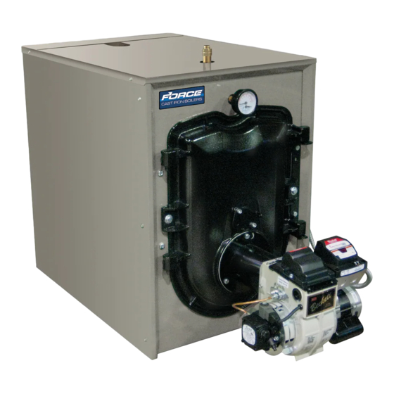
FORCE™ OIL
Residential
Models:
• FORCEOL84-E
• FORCEOL115-E
• FORCEOL140-E
• FORCEOL182-E
Manual Contents
General Information . . . . . . . . . . . . . . . . . . . . . . 5
Pre-installation . . . . . . . . . . . . . . . . . . . . . . . . . . 7
Packaged Boiler Assy . - Trim & Controls . . . . . 9
Water Boiler Piping . . . . . . . . . . . . . . . . . . . . . 17
Indirect Water Heater Piping . . . . . . . . . . . . . . 21
Natural Draft Venting (Chimney) . . . . . . . . . . . 22
Direct Venting/Air Intake Piping . . . . . . . . . . . 26
Electrical . . . . . . . . . . . . . . . . . . . . . . . . . . . . . . 33
Oil Piping . . . . . . . . . . . . . . . . . . . . . . . . . . . . . 37
System Start-up . . . . . . . . . . . . . . . . . . . . . . . . 39
Operating . . . . . . . . . . . . . . . . . . . . . . . . . . . . . 46
Service and Maintenance . . . . . . . . . . . . . . . . 48
Boiler Cleaning . . . . . . . . . . . . . . . . . . . . . . . . 50
Troubleshooting . . . . . . . . . . . . . . . . . . . . . . . . 53
Service Parts . . . . . . . . . . . . . . . . . . . . . . . . . . 55
Burner Specifications . . . . . . . . . . . . . . . . . . . 66
Appendix A Aftermarket LWCO . . . . . . . . . . . 66
As an ENERGY STAR
®
has determined that the FORCEOL meet the
ENERGY STAR
guidelines for energy efficiency
®
established by the United States Environmental
Protection Agency (EPA).
TO THE INSTALLER:
Affix these instructions adjacent to boiler.
TO THE CONSUMER:
Retain these instructions for future reference.
106346-06 - 8/19
Page
Partner, U.S. Boiler Company
• High Efficiency
• Oil-Fired, 3-Pass
• Water Boiler
• Natural Draft or Direct Vent
(140-E and 182-E)
9700609
Advertisement
Table of Contents

Related Manuals for Force FORCEOL84-E


Summary of Contents for Force FORCEOL84-E
-
Page 1: Table Of Contents
• Oil-Fired, 3-Pass • Water Boiler Residential • Natural Draft or Direct Vent (140-E and 182-E) Models: • FORCEOL84-E • FORCEOL115-E • FORCEOL140-E • FORCEOL182-E Manual Contents Page General Information . . . . . . . . . . . . . . . . . . . . . . 5 Pre-installation . - Page 2 Installation, Operating & Service Manual FORCE IMPORTANT INFORMATION - READ CAREFULLY All boilers must be installed in accordance with National, State and Local Plumbing, Heating and Electrical Codes and the regulations of the serving utilities . These Codes and Regulations may differ from this instruction manual . Authorities having jurisdiction should be consulted before installations are made .
- Page 3 Installation, Operating & Service Manual FORCE DANGER DO NOT store or use gasoline or other flammable vapors or liquids in the vicinity of this or any other appliance. WARNING • Improper installation, adjustment, alteration, service or maintenance can cause property damage, personal injury or loss of life.
- Page 4 Installation, Operating & Service Manual FORCE WARNING • This boiler contains very hot water under high pressure. DO NOT unscrew any pipe fittings nor attempt to disconnect any components of this boiler without positively assuring the water is cool and has no pressure.
-
Page 5: General Information
Installation, Operating & Service Manual FORCE General Information 106346-06 - 8/19... - Page 6 Installation, Operating & Service Manual FORCE General Information (continued) Table 1A: Dimensional Data (See Figure 1) Dimensions See Figure 1 Heat Transfer Water Content - Actual Shipping Boiler Model Surface Area - Gallons Weight (LB.) “A” “B” “C” Sq. Ft.
-
Page 7: Pre-Installation
Oil Burning Equipment. ANSI/NFPA 31 standard. FORCE OIL boilers can be installed in rooms with clearances from combustible material as listed above. Listed clearances cannot be reduced for alcove or closet installations. - Page 8 Oil Burning Equipment. ANSI/NFPA 31 standard. 2. FORCE OIL boilers can be installed in rooms with clearances from combustible material as listed above. Listed clearances cannot be reduced for alcove or closet installations.
-
Page 9: Packaged Boiler Assy . - Trim & Controls
Installation, Operating & Service Manual FORCE Packaged Boiler Assembly - Trim & Controls Step 6. Lower pipe handles until front A . REMOVE CRATE . adjustable legs touch floor. If necessary, 1. Remove all fasteners at crate skid. place wooden blocks under front legs 2. - Page 10 Installation, Operating & Service Manual FORCE Packaged Boiler Assembly - Trim & Controls (continued) Figure 4A: Partial Front View - Burner Swing Door Mounted to Boiler - Fully Closed and Secured Step 1. Loosen but do not remove left side •...
- Page 11 Installation, Operating & Service Manual FORCE Packaged Boiler Assembly - Trim & Controls (continued) Figure 4B: Top View - Burner Swing Door Mounted to Cast Iron Block Assembly (Jacket Removed for Clarity) 106346-06 - 8/19...
- Page 12 Installation, Operating & Service Manual FORCE Packaged Boiler Assembly - Trim & Controls (continued) 2. Perform routine inspection, service or cleaning side cap screw first . Use an alternating as necessary. tightening method from right side tap bolt to left side tap bolt to tighten door equally until 3.
- Page 13 Installation, Operating & Service Manual FORCE Packaged Boiler Assembly - Trim & Controls (continued) 3. Inspect burner swing door insulation for Step 2. Locate the relief valve piping damage and proper type. supplied with boiler. Apply thread sealant to all joints prior to assembly.
- Page 14 Installation, Operating & Service Manual FORCE Packaged Boiler Assembly - Trim & Controls (continued) Figure 6: Limit Sensor Insertion Step 2. Locate (2) 5/8” cable clamps in parts carton. Secure burner wiring Figure 7: Return Injector Piping and harness to front of jacket right side...
- Page 15 Installation, Operating & Service Manual FORCE Packaged Boiler Assembly - Trim & Controls (continued) Install stainless steel baffles provided in Step 2. Thread 1-1/4" x 1-1/4" x 3/4" NPT miscellaneous parts carton as follows, refer to tee on opposite end of 5" lg. nipple Table 3 and Figure 9: installed in Step a.
- Page 16 Installation, Operating & Service Manual FORCE Packaged Boiler Assembly - Trim & Controls (continued) 7. Close the burner swing door and securely seal the door to the boiler front section by reinstalling the hardware and securing the door using procedure previously outlined in Paragraph D of this section.
-
Page 17: Water Boiler Piping
4. The FORCE OIL is designed to withstand thermal shock from return water temperatures as low as CAUTION 100°F, but prolonged return temperatures of below Maintain minimum ½... - Page 18 Installation, Operating & Service Manual FORCE Water Boiler Piping (continued) 106346-06 - 8/19...
- Page 19 Installation, Operating & Service Manual FORCE Water Boiler Piping (continued) 106346-06 - 8/19...
- Page 20 Installation, Operating & Service Manual FORCE Water Boiler Piping (continued) Figure 11: Recommended Piping for Combination Heating and Cooling (Refrigeration) System 5. If it is required to perform a long term WARNING pressure test of the hydronic system, the The use of a low water cut-off device, while...
-
Page 21: Indirect Water Heater Piping
Installation, Operating & Service Manual FORCE Indirect Water Heater Piping A . CONNECT INDIRECT DOMESTIC WATER Also refer to Figures 10A and 10B. HEATER PIPING as shown in Figures 12A and Refer to instructions furnished with Indirect Water 12B. Heater for additional information. -
Page 22: Natural Draft Venting (Chimney)
3. The FORCE OIL shall be vented into any of the Colder climates are more susceptible to this following: condition. - Page 23 Installation, Operating & Service Manual FORCE Natural Draft Venting (Chimney) (continued) FIRECLAY TILE LINED CHIMNEY NOT LESS THAN 8" X 8" X 15' THIMBLE NOTE: ALL HORIZONTAL VENT PIPE SHOULD SLOPE UPWARD NOT SLOPE UP LESS THAN ONE INCH IN APPROX.
- Page 24 See Tables 9 and 10 for while in this condition may cause a venting more details as a guide. Actual draft and failure and force flue gases into the living temperature measurements may be different space. If the chimney is to be re-lined use the then those values in the table.
- Page 25 Installation, Operating & Service Manual FORCE Natural Draft Venting (Chimney) (continued) D . STACK TEMPERATURE CAUTION 1. The temperature of the flue gases has a significant Use the chimney venting tables as a guide. It effect on the amount of draft created in a vertical...
-
Page 26: Direct Venting/Air Intake Piping
Installation, Operating & Service Manual FORCE Direct Venting / Air Intake Piping A . GENERAL GUIDELINES WARNING 1. Direct Vent system must be installed in accordance This venting system must be installed by a with these instructions and applicable provisions qualified installer (an individual who has been of local building codes. - Page 27 Installation, Operating & Service Manual FORCE Direct Venting / Air Intake Piping (continued) d. Not less than 7 ft above grade when located Table 5: Wall Cutout Dimensions above public walkway. e. Not less than 3 ft (as measured to side of Direct Vent Conversion "L"...
- Page 28 FORCE OIL and the vent tee body. boiler model (see Table 6).
- Page 29 Installation, Operating & Service Manual FORCE Direct Venting / Air Intake Piping (continued) Table 6: Flex Vent / Vent Termination Pipe Diameters Vent Hood Flex Oil Vent Pipe Boiler Flue Outlet * Flue Outlet Collar to Boiler Model Inner Pipe...
- Page 30 Installation, Operating & Service Manual FORCE Direct Venting / Air Intake Piping (continued) 7. Apply sealant; firstly, between the stop bead and retainer bead at the end of the vent termination inner pipe; secondly, between the stop bead and retainer bead at the end of the appliance adapter.
- Page 31 Installation, Operating & Service Manual FORCE Direct Venting / Air Intake Piping (continued) WARNING DO NOT reduce size of air intake pipe. 3. Remove burner from carton. Secure burner to boiler with mounting hardware included with burner swing door. See Figure 26.
- Page 32 Installation, Operating & Service Manual FORCE Direct Venting / Air Intake Piping (continued) 12. Assemble the vacuum relief valve balance weight 14. Install remainder of air intake piping to Direct onto the gate. Refer to the vacuum relief valve Vent Termination air intake collar, securing manufacturer’s instructions for details.
-
Page 33: Electrical
Installation, Operating & Service Manual FORCE Electrical DANGER Positively assure all electrical connections are unpowered before attempting installation or service of electrical components or connections of the boiler or building. Lock out all electrical boxes with padlock once power is turned off. - Page 34 Installation, Operating & Service Manual FORCE Electrical (continued) 106346-06 - 8/19...
- Page 35 Installation, Operating & Service Manual FORCE Electrical (continued) 106346-06 - 8/19...
- Page 36 Installation, Operating & Service Manual FORCE Electrical (continued) NOTE: APPLY THIS BURNER SCHEMATIC TO APPROPRIATE STEAM OR WATER BOILER CONTROL SCHEMATIC, REFER TO Figure 27 NOTE: APPLY THIS BURNER SCHEMATIC TO APPROPRIATE STEAM OR WATER BOILER CONTROL SCHEMATIC, REFER TO Figure 28...
-
Page 37: Oil Piping
Installation, Operating & Service Manual FORCE Oil Piping A . GENERAL WARNING Under no circumstances can copper with sweat 1. Use flexible oil line(s) so the burner swing door style connectors be used. can be opened without disconnecting the oil supply piping. - Page 38 Installation, Operating & Service Manual FORCE Oil Piping (continued) C . TWO PIPE OIL LINES 3. Under no circumstances is a manual shutoff valve to be located on the return line of a two 1. For two piped systems, where more lift pipe system.
-
Page 39: System Start-Up
Installation, Operating & Service Manual FORCE System Start-Up WARNING All boilers equipped with burner swing doors have a potential hazard which can cause severe property damage, personal injury or loss of life if ignored. Before opening swing door, turn off service switch to boiler to prevent accidental firing of burner outside the combustion chamber. - Page 40 Installation, Operating & Service Manual FORCE System Start-Up (continued) D . ADJUST CONTROL SETTINGS with burner c. Disconnect the copper oil connector tube service switch turned “ON”. from nozzle line. 1. SET ROOM THERMOSTAT about 10°F below d. Loosen the two screws securing igniter- room temperature.
- Page 41 Installation, Operating & Service Manual FORCE System Start-Up (continued) 106346-06 - 8/19...
- Page 42 Installation, Operating & Service Manual FORCE System Start-Up (continued) F . START OIL BURNER . m. Loosening the splined nut and lower acorn nut, and, turning the adjustment screw, 1. Open vent fitting on fuel pump. either forward or, rearwards, will adjust the 2.
- Page 43 (see Figure 15) after chimney has reached 4. FLAME FAILURE operating temperature and while burner is The FORCE OIL boiler controls operate the running (at least five minutes). burner automatically. If for unknown reasons See Table 9 at the end of this manual for the burner ceases to fire and the reset button additional details.
- Page 44 Installation, Operating & Service Manual FORCE System Start-Up (continued) Figure 37: Cad Cell Location clean, then replace and readjust oil pressure. If dripping or after burn persist replace fuel pump. TEST CONTROLS . 1. Check thermostat operation. Raise and lower thermostat setting as required to start and stop burner.
- Page 45 Installation, Operating & Service Manual FORCE System Start-Up (continued) NOTE: DO NOT remove "T-T" jumper b. Check Safety Features unless wiring diagram indicates a direct Safe Start: connection from thermostat and/or • Place a jumper across cad cell terminals. tankless heater HydroStat 3250 control •...
- Page 46 Installation, Operating & Service Manual FORCE System Start-Up (continued) c. Allow the temperature to drop below control setting. The burner must restart. d. Boiler installation is not considered complete until this check has been made. 5. CHECK LOW WATER CUT-OFF a.
-
Page 47: Operating
Installation, Operating & Service Manual FORCE Operating Refer to the HydroStat 3250 Installation Instructions and Operating Manual included with these instructions. IMPORTANT This boiler is equipped with a feature that saves energy by reducing the boiler water temperature as the heating load decreases. This feature is equipped with an override which is provided primarily to permit the use of an external energy management system that serves the same function. -
Page 48: Service And Maintenance
Installation, Operating & Service Manual FORCE Service and Maintenance Instructions n. Remove plugs from all available returns A . WATER BOILERS: and wash the water side of the boiler as 1. Filling of boiler and system. thoroughly as possible, using a high- GENERAL —... - Page 49 Installation, Operating & Service Manual FORCE Service and Maintenance Instructions (continued) C . ATTENTION TO BOILER WHILE NOT IN IMPORTANT OPERATION IF, DURING NORMAL OPERATION, IT IS NECESSARY TO ADD MORE WATER THAN NOTICE: If boiler is not used during winter time, it INDICATED BELOW, CONSULT A QUALIFIED must be fully drained to prevent freeze damage.
-
Page 50: Boiler Cleaning
Installation, Operating & Service Manual FORCE Boiler Cleaning WARNING This boiler contains controls which may cause the boiler to shut down and not restart without service. If damage due to frozen pipes is a possibility, the heating system should not be left unattended in cold weather;... - Page 51 Installation, Operating & Service Manual FORCE Boiler Cleaning (continued) Figure 39: Cleaning of Boiler Flueways WARNING The boiler must be connected to an approved chimney in good condition. Serious property damage could result if the boiler is connected to a dirty or inadequate chimney. The interior of the chimney flue must be inspected and cleaned before the start of the heating season and should be inspected periodically throughout the heating season for any obstructions.
- Page 52 Installation, Operating & Service Manual FORCE Boiler Cleaning (continued) Important Product Safety Information: Refractory Ceramic Fiber Product WARNING Some boiler components use materials that contain refractory ceramic fibers (RCF). RCF has been classified as a possible human carcinogen. When exposed to elevated temperatures, RCF may change into crystalline silica, a known carcinogen.
-
Page 53: Troubleshooting
The selection of the nozzle supplied amount of dirt. with the FORCE OIL boiler is the result of extensive testing to obtain the best flame 6. WATER — Water in the fuel in large amounts shape and efficient combustion. - Page 54 Installation, Operating & Service Manual FORCE Troubleshooting (continued) NOTICE: CHECK TEST PROCEDURE. A very e. Excessive back pressure causing flame to good test for isolating fuel side problems is to be erratic. disconnect the fuel system and with a 24" length 3.
-
Page 55: Service Parts
Installation, Operating & Service Manual FORCE Service Parts All FORCE™ Repair Parts may be obtained by contacting your local Ferguson branch. 106346-06 - 8/19... - Page 56 Installation, Operating & Service Manual FORCE Service Parts (continued) 106346-06 - 8/19...
- Page 57 Installation, Operating & Service Manual FORCE Service Parts (continued) FORCE OIL Bare Boiler Assembly Item Description Part Number FORCEOL84-E FORCEOL115-E FORCEOL140-E FORCEOL182-E 109554-02 Block Assembly Includes: Block 109554-03 Assembly and Smoke Box 109554-04 Smoke Box Includes: 109555-01 Sealant, and Hardware...
- Page 58 Installation, Operating & Service Manual FORCE Service Parts (continued) 106346-06 - 8/19...
- Page 59 Installation, Operating & Service Manual FORCE Service Parts (continued) Item FORCEOL84- FORCEOL115- FORCEOL140- FORCEOL182- Description Part Number 106443-02 Complete Jacket Carton Includes: 106443-03 Labels and Hardware 106443-04 109553-02 Wrap Around Insulation 109553-03 109553-04 Temperature & Pressure Gauge 105894-01 HydroStat 3250 Plus Includes: Remote Mounting Kit &...
- Page 60 4. FLEX OIL VENT PIPE FOR DIRECT VENT 5" Dia. x 10 ft. FOVP-510 100212-02 Not Shown 5" Dia. x 20 ft. FOVP-520 100214-02 5 . FORCEOIL Oil Burners Item Description Part Number FORCEOL84-E FORCEOL115-E FORCEOL140-E FORCEOL182-E 102415-01 102415-02 Natural Draft 102415-03 Beckett 102415-04 Shown 106109-03...
- Page 61 Installation, Operating & Service Manual FORCE Service Parts (continued) 106346-06 - 8/19...
- Page 62 FORCE Service Parts (continued) BECKETT AFG OIL BURNER PART NOS . FOR FORCE OIL SERIES BOILERS NATURAL DRAFT APPLICATIONS NOTE: When ordering parts always give the serial and model numbers shown on the boiler and burner. Also provide the name of the part(s) and part number as listed below.
- Page 63 Installation, Operating & Service Manual FORCE Service Parts (continued) 106346-06 - 8/19...
- Page 64 FORCE Service Parts (continued) BECKETT NX OIL BURNER PART NOS . FOR FORCE OIL SERIES BOILERS DIRECT VENT APPLICATIONS NOTE: When ordering parts always give the serial and model numbers shown on the boiler and burner. Also provide the name of the part(s) and part number as listed below.
- Page 65 Installation, Operating & Service Manual FORCE Burner Specifications Approx. Baffles Stack Baffles IN Approx. Burner Pump Head Insertion Approx. Baffle Temp. Approx. Burner Air Band Breech Approx. Boiler Model Input Nozzle Shutter Pressure Type Depth Shipped Location Increase Overfire Model...
-
Page 66: Burner Specifications
Installation, Operating & Service Manual FORCE Appendix A: Aftermarket Low Water Cut Off (LWCO) On Hot Water Boilers WARNING • DO NOT ATTEMPT to cut factory wires to install an aftermarket Low Water Cut Off (LWCO). Only use connections specifically identified for Low Water Cut Off. - Page 67 Installation, Operating & Service Manual FORCE Appendix A: Aftermarket Low Water Cut Off (LWCO) On Hot Water Boilers (continued) A 24 VAC LWCO is used primarily for gas fired How to Test boilers where a 24 volt control circuit exists within Shut off fuel supply.
- Page 68 Installation, Operating & Service Manual FORCE SERVICE RECORD DATE SERVICE PERFORMED __________________________________________________________________________________________________ __________________________________________________________________________________________________ __________________________________________________________________________________________________ __________________________________________________________________________________________________ __________________________________________________________________________________________________ __________________________________________________________________________________________________ __________________________________________________________________________________________________ __________________________________________________________________________________________________ __________________________________________________________________________________________________ __________________________________________________________________________________________________ __________________________________________________________________________________________________ __________________________________________________________________________________________________ __________________________________________________________________________________________________ __________________________________________________________________________________________________ __________________________________________________________________________________________________ __________________________________________________________________________________________________ __________________________________________________________________________________________________ __________________________________________________________________________________________________ __________________________________________________________________________________________________ __________________________________________________________________________________________________ __________________________________________________________________________________________________ __________________________________________________________________________________________________ __________________________________________________________________________________________________ __________________________________________________________________________________________________ __________________________________________________________________________________________________ __________________________________________________________________________________________________ __________________________________________________________________________________________________ __________________________________________________________________________________________________ __________________________________________________________________________________________________...
Need help?
Do you have a question about the FORCEOL84-E and is the answer not in the manual?
Questions and answers