Advertisement
Quick Links
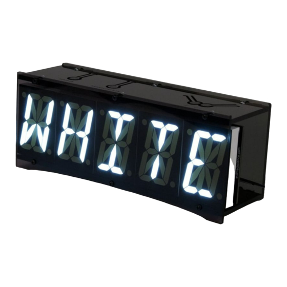
Alpha Clock Five
Alphanumeric LED Clock & Data Display Devices
An open-source hardware+software project. For support links,
design files, source code, & additional documentation,
please visit: https://wiki.evilmadscientist.com/alpha
For version 2.0 kits
– Red,White, and Blue Editions –
Manual v. 2.2
evilmadscientist.com
© 2018 Evil Mad Science LLC
Advertisement

Related Manuals for Evil Mad Scientist Alpha Clock Five

Summary of Contents for Evil Mad Scientist Alpha Clock Five
- Page 1 Alpha Clock Five Alphanumeric LED Clock & Data Display Devices An open-source hardware+software project. For support links, design files, source code, & additional documentation, please visit: https://wiki.evilmadscientist.com/alpha For version 2.0 kits – Red,White, and Blue Editions – Manual v. 2.2 evilmadscientist.com...
- Page 2 In those steps, please pay careful attention to follow the instructions labeled for your color of clock. (There are also “Basic Edition” Alpha Clock Five kits, which are normal Alpha Clock Five kits except that they do not include the Chronodot module or acrylic case.) Acrylic Case...
- Page 3 Assembly Step 2 – Tool Checklist Alpha Clock Five is a soldering kit. You’ll need certain tools and supplies to build it. Four Essential tools: Needed to build the kit: 4. Screwdriver Phillips-head screwdriver, medium size. (#1 is ideal.) 1. Soldering iron A basic soldering iron meant for electronics, with a reasonably fine point tip.
- Page 4 #1 on your bill of materials. Sanity check! This set of instructions is for Alpha Clock Five kits version 2.0, which are based around revisions C/D of the circuit board. To make sure that you’re reading the right set of instructions, confirm at this time that your circuit board says “Rev.
- Page 5 Ohm resistors. Identify them by their the tape straight off to remove it. color code: Brown-Black-Brown-Gold Insert it at location R9 And press it flush to the board Next up: Soldering tips! (the orientation does not matter) [Alpha Clock Five Assembly Guide]...
- Page 6 If not, let it cool and try again. (4). If the component has long and/or or flexible leads, clip off the extra length, close to the board. (But not so close that you’re clipping the board itself.) To be continued... [Alpha Clock Five Assembly Guide]...
- Page 7 Clip the excess leads short. Inspect the solder joints. Make sure that they look shiny, wet, and clean, to ensure a good connection. And finally, repeat this procedure, to install the other #2 resistor at location R5. [Alpha Clock Five Assembly Guide]...
- Page 8 Assembly Step 7 – Install Resistor #3 Next, solder parts #3, two 10 k resistors, into locations R3 and R4. Parts identification: Up close, the color stripes are #3 is the only smaller size resistor. brown-black-orange-gold. [Alpha Clock Five Assembly Guide]...
- Page 9 Part #5 is a 681 ohm “1%” resistor. There’s just one of these. Solder it in at location R1. just one of these. Solder it in at location R2. The color code on this resistor is The resistor’s color code is: orange-yellow-black-black-brown blue-gray-brown-black-brown [Alpha Clock Five Assembly Guide]...
- Page 10 If you are building a WHITE or BLUE Alpha Clock Five , Assembly Step 9 - Resistor packs. skip ahead to the next page , Step 9B . For RED Alpha Clock Five only: Highlighted here are the component locations for JP1, RP3, and RP4 on the circuit board: Parts #6 are two 560 ohm resistor packs.
- Page 11 If you are building a RED Alpha Clock Five , Assembly Step 9B - Resistor packs. skip ahead to the next page , Step 10. For WHITE or BLUE Alpha Clock Five only: Parts #6 are two 10 k ohm (yellow) resistor packs:...
- Page 12 Flip the circuit board over, while keeping To ensure good positioning, rest the The socket pins will protrude (but only the socket in place. circuit board flat on top of the socket. very slightly) through the circuit board [Alpha Clock Five Assembly Guide] [12]...
- Page 13 40-pin socket. Again take care to match just yet– we’ll do that later.) the notches to those on the circuit board Note that each has a notch at one end to mark the polarity. [Alpha Clock Five Assembly Guide] [13]...
- Page 14 Then, solder the other five pins. flush to the circuit board. If not, flip it back over, and melt the joint while pressing down on the circuit board, to snap the header into place. [Alpha Clock Five Assembly Guide] [14]...
- Page 15 In this step, we add the sockets that allow Alpha Clock Five to Assembly Step 13 – RTC Sockets be connected to a real-time clock module (e.g., Chronodot) There are actually two rows of holes at M1. Parts #13 are two 4-pin female Insert the two headers...
- Page 16 Part #14 is the dc power jack. Place it at location J1, on (Red Alpha Clock Five kits include a 2.5 x 5.5 mm jack, while the top side of the circuit board. Blue/White Alpha Clock Five kits include a 2.1 x 5.5 mm jack. ) On the bottom side, solder all three pins in place.
- Page 17 There are two similar types of ceramic capacitors in the kit, so these ones are marked with a black stripe. Solder these two capacitors on the board at locations C5 and C6. [Alpha Clock Five Assembly Guide] [17]...
- Page 18 • For Red Alpha Clock Five: Install six of these capacitors in locations: C1, C2, C3, C7, C8 and C10. • For BLUE / White Alpha Clock Five: Install seven of these capacitors in locations: C1, C2, C3, C7, C8, C10, and C12...
- Page 19 Assembly Step 17 – Quar tz Cr ystal Install part #17, a 16 MHz quartz crystal. Its two pins go in the outer two holes of the location marked “XTL.” Solder both pins in place, much like a resistor. [Alpha Clock Five Assembly Guide] [19]...
- Page 20 Repeat the procedure to add a second Then, on the bottom side, header at location J5, with the pins facing solder all six pins in place. towards the edge of the board as shown. [Alpha Clock Five Assembly Guide] [20]...
- Page 21 Install the LED in location D2, near the top- middle of the board. Orientation matters: The long lead of the LED goes into the square hole of location D2. [Alpha Clock Five Assembly Guide] [21]...
- Page 22 If you are building a RED Alpha Clock Five , skip Assembly Step 20 - Identify Regulator. this step, and advance to the next page , Step 21. For BLUE or WHITE Alpha Clock Five only: Here are two different, but similar looking components in the kit: The six transistors (#20) and the voltage regulator (#21).
- Page 23 Note that each transistor has one flat face. Note that the transistors do not seat fully flush to the circuit board, but rather slightly above it like so. Do not force them down further. [Alpha Clock Five Assembly Guide] [23]...
- Page 24 If you are building a RED Alpha Clock Five , skip Assembly Step 22 - Voltage Regulator. this step and advance to the next page , Step 23. For BLUE or WHITE Alpha Clock Five only: Part #21 is the voltage regulator that you identified in Step 20.
- Page 25 What comes next depends on the For Red Alpha Clock Five Kits: For Blue or White Alpha Clock Five Kits: Install two more capacitors at locations color of your kit... Install one more capacitor into location C9. ...
- Page 26 Assembly Step 24 – Button switches Here is what one of the button locations looks like: Parts #23 are right-angle tactile button switches. “Snap” the button into the location, and make Repeat for each of the switch locations, S1-S5. sure that it sits fully flush to the board. Solder all four pins in place.
- Page 27 Insert the speaker, making sure that the “+” pin goes Solder both pins and clip the leads. into the matching “+” hole on the circuit board. Remove the Kapton tape seal, if present. [Alpha Clock Five Assembly Guide] [27]...
- Page 28 Like the sockets, each chip has a notched end to indicate its polarity. Align that notch to the Blue/White Alpha Clock Five kits also include notch on the socket and on the circuit board. a part #28, which goes into socket U5.
- Page 29 Parts #30 are matching Phillips-head screws. Loosely thread each screw into an angle bracket on the other side of the board. (Do not tighten them yet.) [Alpha Clock Five Assembly Guide] [29]...
- Page 30 It may be helpful to hold the assembly against a hard, flat surface while you do so. Tighten the screws– very securely –to lock the angle brackets in place. [Alpha Clock Five Assembly Guide] [30]...
- Page 31 Assembly Step 29A - The Board So Far skip ahead to the next page , Step 29B . For RED Alpha Clock Five: In the next few steps, we’ll be adding the five alphanumeric LED displays, which will make it harder to access the back side of the circuit board. ...
- Page 32 If you are building a RED Alpha Clock Five , Assembly Step 29B - The Board So Far skip ahead to the next page , Step 30. For BLUE or WHITE Alpha Clock Five: In the next few steps, we’ll be adding the five alphanumeric LED displays, which will make it harder to access the back side of the circuit board. ...
- Page 33 Each display has two rows of ten pins each on the back side. Check these pins carefully, to make sure that they are straight, vertical, and parallel, on each display. If necessary, gently bend them into place. Good! Bad! Also bad! [Alpha Clock Five Assembly Guide] [33]...
- Page 34 Slide one of the 10-position sockets onto the ten pins on one side of an LED display. Make sure that Repeat for both strips of each LED display. it seats all the way down, as shown previously. [Alpha Clock Five Assembly Guide] [34]...
- Page 35 If the displays do not sit neatly, go back and make sure that (1) The LED pins are straight and vertical (Step 28) and (2) The sockets are fully seated (Step 29). [Alpha Clock Five Assembly Guide] [35]...
- Page 36 We’ll add the displays sequentially. Start with the middle display. As with earlier sockets, initially solder Double-check that the socket is properly seated, just the two opposite corner pins. and then solder the remaining socket pins in place. [Alpha Clock Five Assembly Guide] [36]...
- Page 37 Assembly Step 34 – Add remaining alphanumeric displays Install the next two LED displays –at LD2 and LD4 –the same way. Finally, install the outer two alphanumeric LED displays, at locations LD1 and LD5. [Alpha Clock Five Assembly Guide] [37]...
- Page 38 Assembly Step 35 – Light it up! Connect the power supply (#33) and apply power to your clock. (Red versions of Alpha Clock Five come with a 5 V power supply, whereas blue/white versions come with a 9 V power supply.) If all goes well, it will say “HELLO WORLD”...
- Page 39 “Alarm” buttons for 4 seconds to enter the LED Test mode. This will generate a slowly changing LED test pattern that will light up every LED on the front face, to help highlight any assembly issues. [Alpha Clock Five Assembly Guide] [39]...
- Page 40 If you have an older (pre-2.0) version of the Chronodot, where the battery and/or headers need to be soldered in place, please contact Evil Mad Scientist Laboratories for soldering instructions. Important note: Do not set the battery on any conductive surface, or it will drain in a matter of minutes.
- Page 41 The front is either smoke gray or tinted, depending Carefully peel off this wrapping material. on the color of your Alpha Clock Five. Black screws (4-40) #40 Next, we’ll assemble the acrylic clock case. ...
- Page 42 Thread each screw into the corresponding angle bracket. against the bottom of the circuit board, Once both screws from the case bottom are in place, with the back (tabbed) side facing up. tighten them firmly, but take care not to over-tighten. [Alpha Clock Five Assembly Guide]...
- Page 43 –over the tabs on the case bottom. While supporting its weight, insert three of the black 4-40 screws through the top and into the nuts. Tighten them just until they support the weight of the case back. [Alpha Clock Five Assembly Guide]...
- Page 44 T-slots, and end, and slide the top fix it in place with a black 4-40 screw. into place. As before, keep it loose: Only tighten the screws enough to roughly hold the nuts in place. [Alpha Clock Five Assembly Guide]...
- Page 45 Hold the hex nuts flush against the LED displays while you tighten the screws. And, on this side, tighten the three screws firmly. Add three hex nuts to the T-slots along the front-bottom of the clock. [Alpha Clock Five Assembly Guide]...
- Page 46 4-40 screws. If you have trouble getting the case front to reach the case top, the screws on the back side are probably too tight; try loosening them a bit. [Alpha Clock Five Assembly Guide]...
- Page 47 If not– if the top piece is too high or too low – you may need to slightly loosen one or more of the front-top screws to move the case top where it needs to go. [Alpha Clock Five Assembly Guide]...
- Page 48 LED displays do not sit completely vertical in the case, but lean back at a slight angle. This is normal and expected. 4. Tighten the screws here, 3. Tighten the screws on the front-bottom here, on the rear-bottom [Alpha Clock Five Assembly Guide]...
- Page 49 This completes the assembly of Alpha Clock Five. Please see the User Interface Guide (on the following page) to learn how to operate your clock. Please visit our wiki site, https://wiki.evilmadscientist.com/alpha for much more additional documentation For technical support, please visit our Clock support forum, http://www.evilmadscientist.com/forum/...
-
Page 50: Alarm On/Off
+/– using +/– Simultaneous press and hold Simultaneous press and hold (4 seconds): Hold pair Show firmware version & (2 seconds): Enter (or leave) LED test mode Enter (or leave) settings menu [Alpha Clock Five Usage Notes] shop.evilmadscientist.com... -
Page 51: Time Format
Settings Menu: Use Snooze and Alarm buttons to Alpha Clock Five switch between menu options. Switch between values for each menu option with the “+” and “–” buttons. – Firmware v. 2.0 – User Interface Guide Time Format AM/PM, 24 Hr... - Page 52 Any time that you connect the computer to the clock, the clock is likely to restart. However, you can use the computer to set the time on Alpha Clock Five, or to display text on the alphanumeric display. See the Alpha Clock Five documentation wiki for more information about the serial protocol.
Need help?
Do you have a question about the Alpha Clock Five and is the answer not in the manual?
Questions and answers