Table of Contents
Advertisement
Quick Links
Advertisement
Table of Contents

Summary of Contents for MUSTOOL MDS 2112P
- Page 1 MDS 2112P Digital Storage Oscilloscope Quick Guide...
- Page 2 General Warranty We warrant that the product will be free from defects in materials and workmanship for a period of 3 years from the date of purchase of the product by the original purchaser from our company. The warranty period for accessories such as probes is 12 months. This warranty only applies to the original purchaser and is not transferable to a third party.
-
Page 3: Table Of Contents
Table of Contents 1. General Safety Requirements ..................1 2. Safety Terms and Symbols ....................2 3. Quick Start ........................4 Introduction to the Structure of the Oscilloscope ..............4 Front Panel.............................. 4 Rear Panel ............................... 5 Control Area ............................6 User Interface Introduction ...................... -
Page 4: General Safety Requirements
1.General Safety Requirements 1. General Safety Requirements Before use, please read the following safety precautions to avoid any possible bodily injury and to prevent this product or any other connected products from damage. In order to avoid any contingent danger, ensure this product is only used within the range specified. -
Page 5: Safety Terms And Symbols
2.Safety Terms and Symbols 2. Safety Terms and Symbols Safety Terms Terms in this manual. The following terms may appear in this manual: Warning: Warning indicates the conditions or practices that could result in injury or loss of life. Caution: Caution indicates the conditions or practices that could result in damage to this product or other property. - Page 6 2.Safety Terms and Symbols To avoid body damage and prevent product and connected equipment damage, carefully read the following safety information before using the test tool. This product can only be used in the specified applications. Warning The two channels of the oscilloscope are not electrically isolated. The channels should adopt a common ground during measuring.
-
Page 7: Quick Start
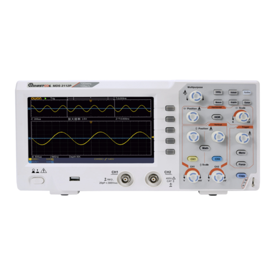
3.Quick Start 3. Quick Start Introduction to the Structure of the Oscilloscope This chapter makes a simple description of the operation and function of the front panel of the oscilloscope, enabling you to be familiar with the use of the oscilloscope in the shortest time. -
Page 8: Rear Panel
3.Quick Start Rear Panel Figure 3-2 Rear Panel 1. Handle 2. Air vents 3. AC power input jack 4. Foot stool: Adjust the tilt angle of the oscilloscope. 5. USB Device port: It is used to transfer data when external USB equipment connects to the oscilloscope regarded as "slave device". -
Page 9: Control Area
3.Quick Start Control Area Figure 3-3 Control Area Overview 1. Function button area: Total 6 buttons. 2. Horizontal control area with 1 button and 2 knobs. "HOR" button refer to horizontal system setting menu, "Horizontal Position" knob control trigger position, " Horizontal Scale" control time base. 3. -
Page 10: User Interface Introduction
3.Quick Start User Interface Introduction 17 16 Figure 3-4 Illustrative Drawing of Display Interfaces 1. Waveform Display Area. 2. Run/Stop 3. The state of trigger, including: Auto: Automatic mode and acquire waveform without triggering. Trig: Trigger detected and acquire waveform. Ready: Pre-triggered data captured and ready for a trigger. -
Page 11: How To Implement The General Inspection
3.Quick Start Falling edge triggering Video line synchronous triggering Video field synchronous triggering The reading shows the trigger level value of the corresponding channel. 14. It indicates the measured type and value of the corresponding channel. "T" means period, "F" means frequency, "V" means the average value, "Vp" the peak-peak value, "Vr"... -
Page 12: How To Implement The Function Inspection
3.Quick Start If it is found that the packaging carton or the foamed plastic protection cushion has suffered serious damage, do not throw it away first till the complete device and its accessories succeed in the electrical and mechanical property tests. 2. -
Page 13: How To Implement The Probe Compensation
3.Quick Start Figure 3-5 Auto set Check CH2 by repeating Step 2 and Step 3. How to Implement the Probe Compensation When connect the probe with any input channel for the first time, make this adjustment to match the probe with the input channel. The probe which is not compensated or presents a compensation deviation will result in the measuring error or mistake. -
Page 14: How To Set The Probe Attenuation Coefficient
3.Quick Start Figure 3-7 Adjust Probe How to Set the Probe Attenuation Coefficient The probe has several attenuation coefficients, which will influence the vertical scale factor of the oscilloscope. To change or check the probe attenuation coefficient in the menu of oscilloscope: (1) Push the function menu button of the used channels (CH1 or CH2 button). -
Page 15: How To Use The Probe Safely
3.Quick Start How to Use the Probe Safely The safety guard ring around the probe body protects your finger against any electric shock, shown as Figure 3-9. Figure 3-9 Finger Guard Warning: To avoid electric shock, always keep your finger behind the safety guard ring of the probe during the operation. - Page 16 3.Quick Start Figure 3-10 Vertical Control Zone 1. Use the Vertical Position knob to show the signal in the center of the waveform window. The Vertical Position knob functions the regulating of the vertical display position of the signal. Thus, when the Vertical Position knob is rotated, the pointer of the earth datum point of the channel is directed to move up and down following the waveform.
-
Page 17: Introduction To The Horizontal System
3.Quick Start Introduction to the Horizontal System Shown as Figure 3-11, there are a button and two knobs in the Horizontal Controls. The following practices will gradually direct you to be familiar with the setting of horizontal time base. Figure 3-11 Horizontal Control Zone 1. -
Page 18: How To Measure Automatically
3.Quick Start 1. Push the Trigger Menu button and call out the trigger menu. With the operations of the menu selection buttons, the trigger setting can be changed. 2. Use the Trigger Level knob to change the trigger level setting. By turning the Trigger Level knob, the trigger indicator in the screen will move up and down. -
Page 19: Communication With Pc
4.Communication with PC 4. Communication with PC The oscilloscope supports communications with a PC through USB port. You can use the Oscilloscope communication software to store, analyze, display the data and remote control. To learn about how to operate the software, you can push F1 in the software to open the help document. -
Page 20: Appendix
5.Appendix 5. Appendix Appendix A: Enclosure (The accessories subject to final delivery.) Standard Accessories: Power Cord CD Rom Quick Guide USB Cable Probe Probe Adjust Options: Soft Bag Appendix B: General Care and Cleaning General Care Do not store or leave the instrument where the liquid crystal display will be exposed to direct sunlight for long periods of time. -
Page 21: Appendix C: Usb Disk Requirements
5.Appendix or fresh water. To avoid damage to the instrument or probe, do not use any corrosive chemical cleaning agent. Warning: Before power on again for operation, it is required to confirm that the instrument has already been dried completely, avoiding any electrical short circuit or bodily injury resulting form the moisture.
Need help?
Do you have a question about the MDS 2112P and is the answer not in the manual?
Questions and answers