Table of Contents
Advertisement
Quick Links
Advertisement
Table of Contents

Related Manuals for dixell EMERSON iCHiLL IC70CX

Summary of Contents for dixell EMERSON iCHiLL IC70CX
- Page 1 IC70CX (doc. rel. 1.1)
-
Page 2: Table Of Contents
Index GENERAL WARNING ............................3 HARDWARE ................................. 4 FRONT PANEL ..............................5 FIRST INSTALLATION ............................6 PARAMETER PROGRAMMING WITH “HOTKEY” ....................6 PARAMETER PROGRAMMING ..........................6 HOW TO LOCK THE KEYBOARD ........................7 MAXIMUM AND MINIMUM TEMPERATURE MEMORIZATION ................7 SET POINT VISUALIZATION AND MODIFICATION .................... -
Page 3: General Warning
Fit the probe where it is not accessible by the End User. The instrument must not be opened. In case of failure or faulty operation send the instrument back to the distributor or to “Dixell S.r.l.” (see address) with a detailed description of the fault. -
Page 4: Hardware
2. Hardware N° OF KEYS RELAY OUTPUT DIGITAL INPUT Config PROBES 2 (NTC o Ptc) Config SERIAL OUTPUT TTL (ModBusRtu protocol) SUPPLY 230 Vac (± 10%) 110 Vac (± 10%) DISPLAY 3 digit with decimal point OTHER Buzzer ... -
Page 5: Front Panel
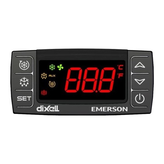
3. Front panel Display symbol MEANING Lighted Compressor ON Blink Compressor start up phase Lighted Defrost on going Blink Dripping time on going Lighted Fan ON Blink Fan start up phase Lighted Alarm ON Lighted Anti legionella cycle on going Lighted Heater ON °C/°F Lighted... -
Page 6: First Installation
4. First installation 4.1 How to set current time Following first power on or after a pediod of power off it’s necessary to program the time and day: Enter the Pr1 programming menu, by pushing the SET + keys for 3s. The rtc parameter is displayed. -
Page 7: How To Lock The Keyboard
6.3 How to move a parameter from the hidden menu (Pr2) to the first level (Pr1) and viceversa Each parameter present in the HIDDEN MENU can be removed or moved into “THE FIRST LEVEL” (user level) by pressing “SET + ”. - Page 8 The type of the probes can be selected by C05 parameter: C05=PTC PTC probes are used C05=NTC NTC probes are used The unit of measure of the temperature can be: C06=°C temperatures are showed in °C C06=°F temperatures are showed in °F ...
- Page 9 10.3 Compressor and heaters regulation in relation to ambient temperature It is possible to set an ambient temperature (parameter S08) under witch the heaters, if not previously ON, are switched ON. It is also possible to switch OFF the compressor if the ambient temperature falls below a determined temperature (parameter S10).
- Page 10 10.4 How to disable the compressor It is possible to disable the compressor pressing key for 3 seconds. If the heaters are available, they are used to substitute the compressor. If the compressor is disabled, it remains in that state also after a power off. 10.5 Fan Fan operation mode can be set by F01 parameter: ...
- Page 11 10.6 Anti legionella cycle The Anti-Legionella cycle is a procedure used to eliminate legionella bacteria; during the cycle the water temperature is increased to S12 set point for a period of time defined by parameter S16 (expressed in tens of minutes). Anti-legionella cycle can be activeted: At Power-On: if the parameter S14=y, the cycle is activated every time the instrument is switched on.
- Page 12 ANTI-LEGIONELLA TIME OUT ALARM When the cycle starts, the controller activates the compressor or the heaters until the temperature reaches the set point value legionella. If the compressor can not be activated because an alarm block it, the heaters are switched on to substitute the compressor. When the anti legionella cycle starts, a maxim time to reach the set point starts counting;...
-
Page 13: Alarms
Defrost visualization It is possible to chooose what to visualize during defrost and dripping time. If d08=it (visualization of the temperature measured when the defrost starts) it valid only if C02=P1 or C02=dtr, otherwise the display shows actual temperature. Defrost visualization: parameter d08 = rt default temperature visualization (parameter C22) parameter d08= it... -
Page 14: Serial Communication
Message Cause Outputs “CA” Pressure switch alarm All outputs OFF (C15=PAL) “rtc” Real time clock alarm Alarm output ON; Other outputs unchanged; Defrosts according to par. “d03” Set real time clock has to be set Real time clock board failure Alarm output ON;... -
Page 15: Parameters
13. Parameters Access to clock menu Hour Minutes Day of the week S 01 S03 S04 0,1 °C / 1°F Set point S 02 0,1°C ÷ 25,5°C 0,1°C / 1°F 1°F ÷ 45°F Differential -55,0°C ÷ S01 S 03 0,1°C / 1°F Minimum value of the set point -67°F ÷... - Page 16 -12,0°C ÷ 12,0°C C 11 0,1°C / 1°F Pb1 Regulation probe calibration -21°F ÷ 21°F -12,0°C ÷ 12,0°C C 12 0,1°C / 1°F Pb2 Evaporator probe calibration -21°F ÷ 21°F -12,0°C ÷ 12,0°C C 13 0,1°C / 1°F Pb3 probe calibration -21°F ÷...
- Page 17 F 04 0÷15 (min.) 1°C / 1°F Fan on time with compressor off F 05 0÷15 (min.) 1°C / 1°F Fan off time with compressor off A 01 rE(0) - Ab(1) Temperature alarms configuration nP(0) - P1(1) - P2(2) - A 02 P3(3) - P4(4) Probe selection for temperature alarms...
- Page 18 rtC Real time clock menu: to set the time and date and defrost start time. TO SET CURRENT TIME AND WEEKLY HOLIDAYS Current hour (0 ÷ 23 h) Current minute (0 ÷ 59min) dAY Current day of the week (Sun ÷ SAt) REGULATION S01 Set point Regulation set point (S3 ...
- Page 19 C19 Fourth relay configuration ( dEF - FAn – ALr - AUS - OnF- HEt) C20 Not used C21 Not used C22 Not used C23 Software release (only reading) C24 Parameter table code (only reading) C25 Serial address (0÷244) C26 Kind of action of auxiliary regulation; CL = cooling, HT = heating C27 Set point auxiliary regulation Auxiliary regulation set point C28 Differential auxiliary regulation Auxiliary regulation differential C29 Auxiliary regulation stopped during defrost;...
- Page 20 n = no: compressor keeps on working; Y = yes, compressor is switched off till the alarm is present, in any case regulation restarts after C02 time at minimum A08 Compressor and heater off with boiler high temperature alarm: n = no: compressor keeps on working; Y = yes, compressor is switched off till the alarm is present, in any case regulation restarts after C02 time at minimum A09 Exclusion of temperature alarm at startup: (from 0.0 min to 23.5h) time interval between the detection of the temperature alarm condition after instrument power on and alarm signalling.
-
Page 21: Installation And Mounting
14. Installation and mounting Instrument IC70CX shall be mounted on vertical panel, in a 29x71 mm hole, and fixed using the special bracket supplied. The temperature range allowed for correct operation is 060 °C. Avoid places subject to strong vibrations, corrosive gases, excessive dirt or humidity. - Page 22 TTL seral port to connect an Hotkey (for parameter programming) or to connect a Personal Computer for parameters programming using Wizmate software Relay configuration - dEF = defrost - Fan = fan - ALr = alarm - AUS = auxiliary - OnF = always on if controller on - HEt = heaters Digital input configuration...
-
Page 23: Technical Data
17. Technical data Housing: self extinguishing ABS Case: frontal 32x74 mm; depth 60mm Mounting: panel mounting in a 71x29mm panel cut-out Protection: IP20; Frontal protection: IP65 Connections: Screw terminal block 2,5 mm wiring Power supply: according to the model: 230Vac 10%, 50/60Hz, 110Vac 10%, 50/60Hz Power absorption: 3VA max Display: 3 digits, red LED, 14,2 mm high;...
Need help?
Do you have a question about the EMERSON iCHiLL IC70CX and is the answer not in the manual?
Questions and answers