Table of Contents
Advertisement
Quick Links
Advertisement
Table of Contents

Subscribe to Our Youtube Channel
Summary of Contents for BEIER-Electronic USM-RC-3
- Page 1 Sound module USM-RC-3 Operating manual Sound Module USM-RC-3 V1.00 BEIER-Electronic Winterbacher Str. 52/4, 73614 Schorndorf - Weiler Telefon 07181/46232, Telefax 07181/45732 eMail: modellbau@beier-electronic.de Internet: http://www.beier-electronic.de/modellbau 11.10.2021 BEIER-Electronic...
-
Page 2: Table Of Contents
Sounds ........................30 Engine sound ......................31 Turning on/off engine sound ..................34 Engine sound 2 ......................35 Functions of USM-RC-3 ................... 36 Additional sounds 1 - 30 ................... 37 Random sounds ....................... 39 WAV-Player ......................39 Functional assignment at proportional channels ............41 Stick simulation via switches or buttons .............. - Page 3 Current monitoring ....................58 LEDs on USM-RC-3 ....................59 Kraftwerk EasyBus lighting boards ................60 PC software „USM-RC-3 Sound-Teacher“ ............... 61 Using software „USM-RC-3 Sound-Teacher“ ............63 Saving sounds and configurations on SD card ............98 Transferring configurations with data cable K-USB-2 ..........99 Adjustments of driving sound with the driving sound diagram ........
-
Page 4: Introduction
• WAV player (ideal for playing music) Light functions: The USM-RC-3 has 16 switching outputs to which LEDs, lamps and relays, for example, can be connected to enable various lighting effects. Light functions such as dipped headlights, reversing lights, brake lights, turn signals, hazard lights, flickering lights, etc. -
Page 5: Safety Notes
YouTube tutorials If you have questions about basic functions of the sound module USM-RC-3, please watch our YouTube video tutorials with English subtitles. In these videos we explain for example how to connect the sound module and how to program and control different functions. -
Page 6: Technical Data
Sound module USM-RC-3 Technical data Supply Voltage (U 5 – 15 V DC Power consumption: Standby current: approx. 80 mA Operation: The current consumption depends on the volume and the switched load. Proportional inputs: 8 inputs Supported protocols: • PPM / PCM (1,000 - 2,000 ms) •... -
Page 7: Operating Modes: Digital, Digital Mode With Ufr Speed Controller, Analogue And Mix Mode
Therefore you should decide at the beginning which operating mode is best for your model. The operating mode of the sound module is set in the USM-RC-3 Sound-Teacher (see page Fehler! Textmarke nicht definiert.). If possible, please use Digital or Mix mode, owing to their extended selection of functions. - Page 8 • Additional outputs for lights. When using the combination, we recommend controlling lights with the UFR. In case more lights are required at the UFR, additional light outputs from the USM-RC-3 can be used. The corresponding output functions must be set in the USM-RC-3 Sound-Teacher.
-
Page 9: Pin Assignment Digital Mode
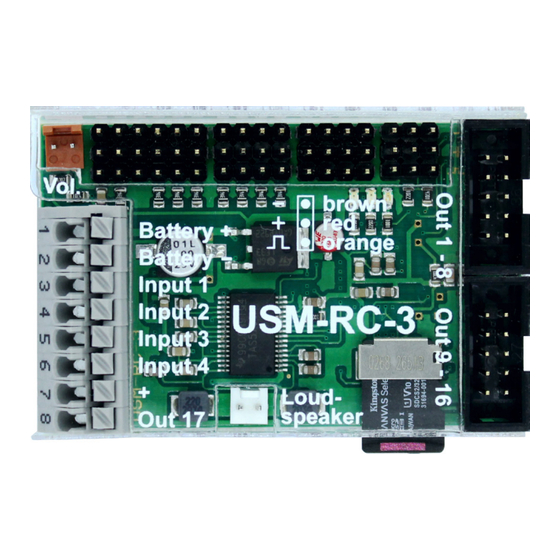
Sound module USM-RC-3 Pin assignment Digital mode X1/1 Battery + (5 – 15 V) X1/2 Battery - X1/3 Input 1 X1/4 Input 2 X1/5 Input 3 X1/6 Input 4 X1/7 Plus connection for outputs (internally connected to X1/1) X1/8 Switching output 17 (high current, max. 3.0 A) -
Page 10: Wiring Diagram Digital Mode
Sound module USM-RC-3 Wiring diagram Digital mode Data cable K-USB-2 IR / BT transmitter Kraftwerk EasyBus 2nd ESC / Steering servo Speed controller Input 4 Input 3 Input 2 Input 1 BEIER-Electronic 11.10.2021... -
Page 11: Pin Assignment Digital Mode With Ufr Speed Controller
Sound module USM-RC-3 Pin assignment Digital mode with UFR speed controller X1/1 Battery + (5 – 15 V) X1/2 Battery - X1/3 Input 1 X1/4 Input 2 X1/5 Input 3 X1/6 Input 4 X1/7 Plus connection for outputs (internally connected to X1/1) X1/8 Switching output 17 (high current, max. -
Page 12: Wiring Diagram Digital Mode With Ufr Speed Controller
Sound module USM-RC-3 Wiring diagram Digital mode with UFR speed controller Data cable K-USB-2 IR / BT transmitter Kraftwerk EasyBus Input 4 Input 3 Input 2 Input 1 BEIER-Electronic 11.10.2021... -
Page 13: Pin Assignment Mix Mode
Sound module USM-RC-3 Pin assignment Mix mode X1/1 Battery + (5 – 15 V) X1/2 Battery - X1/3 Motor 1 + (speed) X1/4 Motor 1 - (speed) X1/5 Motor 2 + (speed) X1/6 Motor 2 - (speed) X1/7 Plus connection for outputs (internally connected to X1/1) X1/8 Switching output 17 (high current, max. -
Page 14: Wiring Diagram Mix Mode
Sound module USM-RC-3 Wiring diagram Mix mode Data cable K-USB-2 IR / BT transmitter Kraftwerk EasyBus Steering servo BEIER-Electronic 11.10.2021... -
Page 15: Pin Assignment Analog Mode
Sound module USM-RC-3 Pin assignment Analog mode X1/1 Battery + (5 – 15 V) X1/2 Battery - X1/3 Motor 1 + (speed) X1/4 Motor 1 - (speed) X1/5 Motor 2 + (speed) X1/6 Motor 2 - (speed) X1/7 Plus connection for outputs (internally connected to X1/1) X1/8 Switching output 17 (high current, max. -
Page 16: Wiring Diagram Analog Mode
Sound module USM-RC-3 Wiring diagram Analog mode Data cable K-USB-2 IR / BT transmitter Kraftwerk EasyBus e.g. switching module BEIER-Electronic 11.10.2021... -
Page 17: Installation
USM-RC-3 cover. Pay attention not to connect components and conductor tracks with any metal parts! This may cause a short circuit, which destroys the USM-RC-3! Connection The connection of the supply voltage, the loudspeaker and the outputs are always the same, regardless of whether the module is operated in Digital, Analog or Mixed mode. - Page 18 Of course other cables/plugs with a cross section of 0,14 mm² - 0,5 mm² can be connected as well. The USM-RC-3 is always switching the negative pole to each output and thus to the connected load. The negative pole is always connected to the load (see wiring diagram).
- Page 19 Black The switched voltage at the outputs (with 100% intensity) is always as high, as the supply voltage of the USM-RC-3. For example if the module is supplied with 12V, only lamps with 12V should be connected. If you want to connect LEDs, series resistors are always required. Furthermore, attention must be paid to the correct polarity of the LED.
- Page 20 The speed controller is not powered by the data cable. For using the data cable, the USM-RC-3 must be supplied with power via the battery as normal. General remarks for wiring Always use cables with a core diameter of at least 0.75 mm² for connecting the power supply.
-
Page 21: Connection Of Sound Module In Digital Mode
Sound module USM-RC-3 Connection of sound module in Digital mode Connection of proportional channels Up to eight proportional outputs of an RC receiver can be attached to connectors X2/1 - X2/8. Just use the two supplied servo patch cables for the connection. If more than two proportional channels should be connected, further servo patch cables are required. - Page 22 Sound module USM-RC-3 Connection of switching-inputs You can use the switching-inputs at the terminals X1/3 – X1/6 to trigger four different functions (see page Fehler! Textmarke nicht definiert.). All switching-inputs of the sound module are negative switching. To trigger a function, you have to connect the negative pole of the power supply to the corresponding input.
-
Page 23: Connection Of Sound Module In Digital Mode With Ufr Esc
Sound module USM-RC-3 Connection of sound module in Digital mode with UFR ESC Connection to UFR-1230 speed controller The sound moduel pin header X2/1 is connected to the pin strip X4/1 (bottom) of the speed controller with one of the supplied servo patch cables. With this connection the sound module receives all information about speed and light settings. - Page 24 Sound module USM-RC-3 All switching-inputs of the sound module are negative switching. To trigger a function, you have to connect the negative pole of the power supply to the corresponding input. Generally switching units (such as our OKA-4, RC-SM-4 or other standard multi-switch-modules) are used for this purpose.
-
Page 25: Connection Of Sound Module In Analog Mode
Sound module USM-RC-3 Connection of sound module in Analog mode Connection of motors In the Analog mode, the driving speed is determined by the motor voltage. One or two DC motors can be connected to the terminals X1/3 and X1/4 or X1/5 and X1/6. -
Page 26: Connection Of Sound Module In Mix Mode
Sound module USM-RC-3 Connection of sound module in Mix mode Connection of motors In the Mix mode, the driving speed is determined by the motor voltage. One or two DC motors can be connected to the terminals X1/3 and X1/4 or X1/5 and X1/6. The connection to the sound module is implemented parallel to the existing connections of the speed controllers which powers the motors. - Page 27 Sound module USM-RC-3 Connection of switching-inputs If only 1 motor for driving speed detection is connected to X1/3 and X1/4, the two terminals X1/5 and X1/6 can be used as switching inputs, via which various functions (see page 36) can be triggered.
-
Page 28: Loudspeaker
Loudspeakers with an impedance of at least 4 Ω and a maximum output of at least 8 W can be connected to the USM-RC-3 sound module. We recommend using a full- range loudspeaker with 4 Ω or 8 Ω. Loudspeakers with a higher impedance will of course also work, but the volume will decrease as the impedance increases. -
Page 29: Volume Control
If more than one option to control the volume are used at the same time, then the lowest set volume always controls the maximum volume at the model. The USM-RC-3 also has the "Mute" function, which can be used to switch off the entire sound output of the module. -
Page 30: Sounds
Sound module USM-RC-3 Sounds All sounds are stored at the USM-RC-3 with our software USM-RC-3 Sound-Teacher, in so called „slots". You don’t have to use every slot. If you don’t want e.g. any starting-noise, just keep the starting-noise slot free. -
Page 31: Engine Sound
Sound module USM-RC-3 Engine sound The engine sound consists of several single sounds. Normally there is an engine starting sound, an idling sound, a driving sound and an engine stopping sound. This module also offers the possibility to imitate up to five different driving sounds (for... - Page 32 (e.g. slow, normal and fast). Please keep in mind; the “gears” are just generated by the USM-RC-3 and not through a mechanic gearshift. Yet it is not possible to activate the different sounds through an engine control or a real gearshift.
- Page 33 How to open sound files In the folder “USM-RC-3 Sounds”, on the supplied DVD-ROM, you will find some exemplary sounds for different vehicle types. In order to store a new sound on the USM-RC-3, start the program “USM-RC-3 Sound-Teacher", open a *.sfr project file (Menue “File”...
-
Page 34: Turning On/Off Engine Sound
Sound module USM-RC-3 Turning on/off engine sound The USM-RC-3 can only play an engine sound, if it has been switched on before. There are different ways to switch on the engine sound: Using a proportional channel (X2/2 - X2/8) to switch on engine sound: The engine sound can be switched on and off via a control on the radio (stick / slider / switch / rotary potentiometer). -
Page 35: Engine Sound 2
Sound module USM-RC-3 Engine sound 2 In addition to the actual engine/driving sound; a second speed-dependent sound can also be played. However, this second engine sound does not offer as many sound slots/options as the normal engine sound. The engine sound 2 must not necessarily be an engine sound that is played while "driving". -
Page 36: Functions Of Usm-Rc-3
Sound module USM-RC-3 Functions of USM-RC-3 Additionally to the driving sound, the USM-RC-3 offers more features, which can be controlled by the remote control or the switching-inputs. Overview of all the functions: Additional sounds • Trigger additional sounds 1 - 30 Outputs / Lighting •... -
Page 37: Additional Sounds 1 - 30
Additional sounds 1 - 30 In addition to the engine sound, the USM-RC-3 can play up to 30 additional sounds. Typical sounds are e.g. horns, hydraulic and pneumatic noises, warning horns, shooting noises, Songs, radio calls, and so on. There are nearly no limits set to your imaginations. - Page 38 Sound module USM-RC-3 The possible playback modes are now described. They differ also in that way, how the sound is started. Triggering with proportional channels (as memory configured) or with EKMFA- mode: Mode Function Once / complete When the sound is started, it is played exactly once, from start to finish, and then it stops.
-
Page 39: Random Sounds
Sound module USM-RC-3 Random sounds Up to eight random sounds can be played with the USM-RC-3. The frequency of the sound play-back is determined by a random generator. The time spans (min/max) can programmed by 1 – 999 s for every sound separately. In the same way the conditions (idling/drive - engine sound on/off) the sound should be played can be programmed for each of the 8 random sounds. - Page 40 Sound module USM-RC-3 After track 30 the internal counter will jump back to track 1. By the way, the sound module always remembers the current track number. The next time the power supply is switched on, this track number “will be loaded“ again. If any changes are made to the SD card via the Sound-Teacher, the track counter will be reset to track number one.
-
Page 41: Functional Assignment At Proportional Channels
Sound module USM-RC-3 Functional assignment at proportional channels The proportional channel #1 is only responsible for the speed recognition. If 2 drive motors are used, proportional channel #2 is additionally needed for the speed recognition. The remaining channels can be configured in the Sound-Teacher with different functions. - Page 42 The neutral positions of the proportional channels #1 and #2 are read in again each time the USM-RC-3 is started. It must therefore be ensured that when the USM-RC-3 is switched on, the throttle and steering on the radio are in neutral.
-
Page 43: Stick Simulation Via Switches Or Buttons
Sound module USM-RC-3 Hint: The diagnosis (see page 104) can be used to check which values the sound module receives from the radio. This can be very helpful when troubleshooting. Stick simulation via switches or buttons To use the functions of the proportional... -
Page 44: Nautic Mode / Multiswitch Mode
With correctly received data from the switch module, the blue LED on the USM-RC-3 always flashes at regular intervals. -
Page 45: One-Channel Multi-Function Selection (Ekmfa)
The sum signal output of the receiver is connected to „Prop #8“ (X2/8) at the USM- RC-3. If the USM-RC-3 receives a correct sum signal, the blue LED will flash at regular intervals. Using the Sound-Teacher all 16 channels of the sum signal can be assigned to one of the 16 propotional channels of the USM-RC-3. -
Page 46: Digital Switches At Sum Signal Sumd3
17 outputs by using the Sound- Teacher (see page 80). The USM-RC-3 is always switching the negative pole to each output and thus to the connected load (e.g. LED, lamp, relay). The loads plus pole is connected directly to the supply voltage, or to the black and white cables of the output blocks (collected plus pole). - Page 47 Sound module USM-RC-3 Following output types are possible: • Output static on • Output flashing • Output as pulse • Output flickering (sound dependend) • Daytime running light • Parking light • Low beam headlight • High beam headlight • Front fog light •...
- Page 48 Sound module USM-RC-3 The output types “Parking light”, “Low beam headlight”, “High beam headlight”, “Fog light”, “Rear fog light”, “Indicator left”, “Indicator right” and all “Combined lights” must be switched on via their “light names”, not via the output number! For example, if the parking light is connected to output 1, to switch on the parking light (via a prop.
- Page 49 Sound module USM-RC-3 This can be used to generate very impressive light effects, such as a simulation of fire or a welding torch. The Sound-Teacher allows you to adjust the sensitivity of the flicker effect separately for each of the outputs. A value between 1 and 255 can be entered in the field “Option 1“.The higher the value the higher the sound volume must be to activate...
- Page 50 Sound module USM-RC-3 Outputs “Indicator left“ and “Indicator right“ The outputs for the indicators can be switched on using proportional channel #2, a nautic switch or the EKMFA-mode. If “American indicator mode” is selected, the indicator lights will come on, as soon as the parking light is switched on.
- Page 51 Sound module USM-RC-3 For each of this light functions you can set the intensity separately. The intensity for “Parking light” is set at “Intensity” for example 10 %. The intensity for “Brake light” is set at “Option 1” for example 100 %.
- Page 52 Sound module USM-RC-3 Output „Stationary/Motion“ With this function the output is always active, regardless of whether the model is moving or not. The value “Intensity” defines the light intensity during standing. “Option 1” defines the intensity when the model is in motion (0 – 100 %). The change between both light intensities is executed smoothly.
- Page 53 Sound module USM-RC-3 Some of the available functions are mutually exlusive. For example, a ship cannot be “At anchor“ and be “In operation“ at the same time. The relationship between light functions and outputs (see table), are fixed and can not be changed! The condition "in operation"...
-
Page 54: Output Sequences
The outputs 1 - 12 of the USM-RC-3 can be transmitted to our IR light module IR-16-2 via an infrared signal. The outputs 1 - 16 of the USM-RC-3 can be transmitted via infrared signal to our light module LM-IR-16-4 or via Bluetooth to the light module LM-BT-16-4. -
Page 55: Servo Outputs
Sound module USM-RC-3 Servo outputs The USM-RC-3 offers 4 servo outputs (X5/1 - X5/4). The servo outputs deliver usual pulses from 1.000 – 2.000 ms, so you can connect standard servos or speed-controllers. The power for the servo outputs is supplied from the proportional inputs #1 - #8 using the connections X2/1 - X2/8. - Page 56 Sound module USM-RC-3 movement. So you can play for every direction of running a different sound. If you don’t want sounds while moving the servos, just leave these sound-slots empty. BEIER-Electronic 11.10.2021...
-
Page 57: Function Sequences
Sound module USM-RC-3 Function sequences All functions that can be triggered with the sound module (see page 36) can be compiled to a special function sequence with defined order and time for each step. More information can be found in this manual starting on page 94. -
Page 58: Current Monitoring
Sound module USM-RC-3 Lithium – iron 6,6 V (2 cells) 5,0 V 4,5 V phosphate (LiFe) 9,9 V (3 cells) 7,5 V 6,6 V 13,2 V (4 cells) 10,0 V 8,8 V These values are only guidelines, the best is to read the user manual of the battery, to find out the exact deep-discharge voltage. -
Page 59: Leds On Usm-Rc-3
Sound module USM-RC-3 LEDs on USM-RC-3 There are three LEDs on the sound module to show different conditions. Green LED The green LED allways lights up while the supply voltage is connected to X1/1 and X1/2. Red and blue LED These two LEDs show different conditions and errors. -
Page 60: Kraftwerk Easybus Lighting Boards
The EasyBus lighting boards require at least the software version V4.08 to work with the USM-RC-3. If the lighting boards have an older software version, they can be updated via the Kraftwerk software "ControlPanel" and a KLM. Alternatively, the lighting boards can also be sent to Kraftwerk for an update. -
Page 61: Pc Software „Usm-Rc-3 Sound-Teacher
Sound module USM-RC-3 PC software „USM-RC-3 Sound-Teacher“ With our software „USM-RC-3 Sound-Teacher“ the module can be configured and sound files can be tranfered to the SD-card. System requirements • Windows compatible PC • Windows 2000, NT, XP, Vista, Windows 7, Windows 8 or Windows 10 •... - Page 62 To do this, click on the “Start” button at the bottom left and look for the “USM-RC-3 Sound-Teacher” folder in the list, click on it and then click on “USM-RC-3 Sound-Teacher”. The program should now start.
-
Page 63: Using Software „Usm-Rc-3 Sound-Teacher
Sound module USM-RC-3 Using software „USM-RC-3 Sound-Teacher“ Menue Creates a new project Create new project Open project Opens an existing project Saves the current project Save project Save project as Saves a copy of the current project with a new name... - Page 64 Sound module USM-RC-3 Configuring sounds A lot of different sounds can be saved in the sound slots of the USM-RC-3. The sounds are divided into five different ranges: • Engine sound • Engine sound 2 • Additional sounds • Random sounds •...
- Page 65 Therefore the Sound-Teacher asks, when you are saving a project, to copy all files to the project directory. Configuring the sound module Click on the “configuration“ tab in order to carry out adjustments to the USM-RC-3. The settings are divided up into different ranges: • General •...
- Page 66 If the diagnosis function is activated, the sound playback may be faulty. If EasyBus lighting boards from Kraftwerk are to be controlled by the USM-RC-3, this must be activated here. Further information, see page 60. BEIER-Electronic...
- Page 67 Sound module USM-RC-3 The "Startup function" is always started when the module is switched on (supply voltage applied). Volume You can also configure the basic volume (10-100%) of the module here. This function is helpful if you don’t use a volume control potentiometer. The volume can also be adjusted e.g.
- Page 68 Bluetooth controller: If you want to control the USM-RC-3 via the Android app "SFR-1 Controller" with the Bluetooth module BTC-1, this must be activated here. A 4-digit PIN protects the model from being controlled by others.
- Page 69 Sound module USM-RC-3 Configuration – Engine Sound – Engine Sound Engine sound options At this point you can define whether the model is fitted with one or two motors whose speed dictates the driving sound. If two motors for engine sound are selected, you can decide if an average speed of both motors (and proportional channels) should be used to set the volume of the motor sound.
- Page 70 Sound module USM-RC-3 Cornering squeak: As soon as the vehicle is turning, the cornering speake is played. The higher the value is, the more the steering must be to trigger the cornering squeak. Values between 20 and 127 are possible.
- Page 71 Sound module USM-RC-3 Stationary/motion/gear hysteresis: When the vehicle is moving very slowly and the sound constantly alternates between idle and running sound, then this value should be raised slightly. Also if the engine sound alternates steadily between two speed steps/gears while driving, this value should be raised slightly, as well.
- Page 72 Sound module USM-RC-3 Configuration - Engine Sound - Engine Sound 2 Different parameters for engine sound 2 can be configured in this section. Speed via proportional channels: Here it is determined by which proportional channel the speed of the 2nd engine sound is to be controlled.
- Page 73 Sound module USM-RC-3 Configuration - Random sounds Random sounds If you want to play random sounds (see page 39), you can set the time in which interval a random sounds should be triggered. The time ranges between 1 and 999 seconds.
- Page 74 If sum signals should be used, they must be activated here. The sum signal channel of the receiver is connected to proportional channel #8 (X2/8) of the USM-RC-3. The proportional channels of the USM-RC-3 can be assigned to the sum signal channels (see also page 45).
- Page 75 Sound module USM-RC-3 Configuration - Proportional channels Assignments and thresholds for proportional channel For each of the proportional channels # 2 - # 8 (or # 2 - # 16 when using a sum signal), areas A, B, C and D can be assigned with the possible functions of the sound module.
- Page 76 Configuration - Nautic/Multiswitch If you want to use the nautic mode 1 or 2, you will first have to activate it here and connect the USM-RC-3 prop. channel #3 (X2/3) or #4(X2/4) to the receiver channel. Switch assignment Every switch position can be assigned to a function (see page 36).
- Page 77 Sound module USM-RC-3 Configuration - EKMFA If you want to use EMKFA mode, you have to activate it first. The used functions for EKMFA mode (see page 45) can be configured here. Of course, you don’t have to assign every position (2 x 15 positions).
- Page 78 Kraftwerk. The control pad channel is connected from the receiver output to channel # 3 (X2 / 3) or channel # 4 (X2 / 4) of the USM-RC-3. The control pad can trigger up to 44 functions: •...
- Page 79 Sound module USM-RC-3 Teach-in the control pad: Before using the USM-RC-3 for the first time, it must be taught-in to the control pad or the transmitter. It works like this: 1. Disconnect the sound module from the supply voltage. 2. Switch on the radio and receiver.
- Page 80 Configuration - Outputs The colored small boxes next to each output indicate the color of the flat ribbon cable that is connected to each output at the USM-RC-3. Output type You can assign 17 switching-outputs to various output types/characteristics (see page 46).
- Page 81 Sound module USM-RC-3 Configuration - Outputs - Output options If the function “Light flickering when starting“ is activated, all 16 outputs will flicker while the starting noise (coldstart or warmstart) is played. The light bulb effect can be set in 3 levels: Light, medium and strong.
- Page 82 Sound module USM-RC-3 It can also be specified that indicators will turn off automatically after a certain number of flashes. The indicators can be activated fully automatically as soon as the vehicle is steered and then deactivated again. The steering thresholds for this can be set or adapted separately.
- Page 83 Sound module USM-RC-3 If the option "low beam with xenon HID turn-on effect" is activated, the typical xenon effect (short flash followed by dimming up) appears when turning on the low beam headlight. If desired, parking light and low beam headlight can always be switched on automatically as soon as the engine sound is on.
- Page 84 Sound module USM-RC-3 For "reversing light possible", "brake light possible" and "indicator light possible" a „ “ does not mean that the lights are always switched on. Only when the corresponding function is triggered, the lights will be activated.
- Page 85 Sound module USM-RC-3 With the USM-RC-3 up to 16 outputs can be combined and activated in a defined sequence (duration and intensity). This can be parallel or in a row. In total 8 output sequences can be programmed, each with 36 steps.
- Page 86 Sound module USM-RC-3 Total steps For each sequence, the number of steps can be set here. In each case, up to 36 steps are possible. If you activate the sequence, the steps will start with step 1 and run sequentially.
- Page 87 Sound module USM-RC-3 Output sequence 1: This sequence is a simple rotating light with three lamps/LEDs. In the first step only output 1 is switched on. In the second step output 1 goes off again, and output 2 is switched on. In the third step output 2 is switched off and output 3 is switched on.
- Page 88 Sound module USM-RC-3 Configuration - Servo outputs - Servos sequence 1 + 2 For servo outputs 1 and 2 you can program a time controlled flow sequences. A sequence may consist of up to 10 steps. For every step a servo position (1,000 - 2,000ms) must be assigned, that indicates the starting position of the servo.
- Page 89 Sound module USM-RC-3 Sound at servo movement With this option the sound (additional sound) for the servo is always played as long as the servo moves. Sound when not in home position With this option, the sound will be played when the servo is not in home position (position of step 1).
- Page 90 Configuration - Servo outputs - Servos 1 + 2 The 4 servo outputs (see page 55) of the USM-RC-3 can be configured here. If servo outputs 1 and 2 are to be used, they must be switched on in the Sound- Teacher.
- Page 91 Sound module USM-RC-3 Go automatically to home position if no other position is selected If this option is activated, the servo will go automatically in home position if currently no position #1 - #4 is selected. If this option is not activated, the servo will not go back to home position during deactivation, but stays in the current position.
- Page 92 Sound module USM-RC-3 position, the slider must be moved to the left or right of 1.500 ms (motor off) in the basic position. The values in ms along the lines behind the positions #1 - #4 indicate the maximum engine speed. At the value of 1,000 ms and 2,000 ms, the engine is running forward or backward at full throttle.
- Page 93 Sound module USM-RC-3 If the movement is activated/deactivated with a proportional channel, we recommended to use the function under "In position (static)". 11.10.2021 BEIER-Electronic...
- Page 94 Sound module USM-RC-3 Configuration - Function sequences All functions of the USM-RC-3 (see page 36) can be compiled to a timed sequence of up to 36 functions/steps. For each step a function can be selected and switched on or off. In Duration the time can be defined until the next step is activated.
- Page 95 Configuration – Light module – Light module servos 1 + 2 The servo outputs of the light modules SM-IR-16-2, LM-IR-16-4 and LM-BT-16-4 can be configured similar to the servo outputs of the USM-RC-3. For details about the settings please read page 90 onwards. The only difference is that the light modules has only 2 positions, #1 and #2.
- Page 96 Sound module USM-RC-3 Configuration – Light module – Light module motor To control the motor output the light modules LM-IR-16-4 LM-BT-16-4 there are 2 options: 1. Control the motor output using the "up" / "down" functions: Here the motor can be controlled using the two functions "LM: Motor up"...
- Page 97 Sound module USM-RC-3 Project notes In project notes you have space for remarks about your project and settings. 11.10.2021 BEIER-Electronic...
-
Page 98: Saving Sounds And Configurations On Sd Card
The sound module must be disconnected from the supply voltage before inserting or pulling out the SD card! 1. Pull out the SD card from the slot of the USM-RC-3. The card should be handled with care in order to prevent damage because the side with the golden contacts is very sensitive to scratches. -
Page 99: Transferring Configurations With Data Cable K-Usb-2
USM-RC-3 can not be found with data cable If the USM-RC-3 port can not be found with the data cable, check the port in the device manager. If there is a yellow warning sign a new hardware driver (Prolific) is required. - Page 100 Sound module USM-RC-3 WineBottler. No extra hardware driver is required, however a COM port must be set using following comand in your terminal window: sudo ln -s /dev/cu.usbmodem9f31 ~/"Wine Files"/dosdevices/com5 BEIER-Electronic 11.10.2021...
-
Page 101: Adjustments Of Driving Sound With The Driving Sound Diagram
Explanation of the different coloured lines and quadrates in the diagram Green line The green line indicates the neutral position of the throttle stick. As long as the throttle channel is in the neutral position, the module idles and the USM-RC-3 plays the idle noise. Red lines The red lines on the outside left and right represent the maximal driving speed (backwards and forwards). - Page 102 Sound module USM-RC-3 The thresholds can be adjusted with the red quadrates. As soon as the driving speed reaches the speed at the red line, a change of the driving sound takes place. Depending on the number speed steps/gears the same amount of red lines will appear.
-
Page 103: Sound Simulation
• Button 1 - 0 Additional sound 11 - 20 Testing functions with help of data cable K-USB-2 The function “Control USM-RC-3 functions with data cable” can be found under menu “Data cable”. With the help of the data cable K-USB-2, all functions can be controlled directly from the PC and not only via the remote control. -
Page 104: Diagnosis
Sound module USM-RC-3 Diagnosis A diagnosis function is integrated in the USM-RC-3 to control different functions, values and features. There are two different types of diagnosis: 1. Diagnosis with datacable (live) 2. Diagnosis with SD card (recorded) The diagnosis window is divided into different areas: proportional channels, outputs, servo outputs, motor, nautic mode and others. - Page 105 The additional datacable K-USB-2 is needed for live-diagnosis. It is connected to X11. The brown cable points to the edge of the board.. A live-diagnosis using the data cable is generally only useful when the USM-RC-3 in the model is completely installed; wired and all necessary equipment is switched on (e.g.
- Page 106 Sound module USM-RC-3 Record diagnosis with SD card You can also record diagnosis data from the USM-RC-3 to the SD card. This data can be displayed with the Sound-Teacher on the computer. Consider following points: • The must be enabled first in the Sound-Teacher.
-
Page 107: Firmware Update
The sound-Teacher writes the firmware file automatically while saving the project data onto SD card. A firmware update of the USM-RC-3 is always performed automatically when the Sound-Teacher version is different from the current version of the USM-RC-3 firmware. The firmware update will be started after the supply voltage is switched on and it takes 10 seconds. -
Page 108: How To Create New Sounds
Sound module USM-RC-3 How to create new sounds On the supplied DVD-ROM there are plenty of sounds with which you can make your first attempts with the sound speed controller. At some point you will certainly want to play your own sounds on your sound speed controller. - Page 109 Sound module USM-RC-3 Please note that we are not the developer of the “Audacity” software, have no rights to it and cannot offer any further support for this product. The following example explains how you can record sounds with the “Audacity”...
- Page 110 Sound module USM-RC-3 7. The waveform of the recorded sound is shown in blue. You can listen to the recorded sound by clicking the play button (green triangle). The sound can now be edited using the extensive functions of the software. In addition, the sound must also be converted into the appropriate format.
-
Page 111: How To Convert Sound Files
Otherwise the WAV files cannot be played using the sound simulation in the Sound-Teacher! 9. 9. Now the newly created file can be edited further with Audacity or loaded directly with the software "USM-RC-3 Sound-Teacher". 11.10.2021 BEIER-Electronic... -
Page 112: How To Edit Sounds With The Pc
Sound module USM-RC-3 How to edit sounds with the PC "Amplify" sounds So that the sound is played loud enough, the sound must be controlled accordingly. In practice, it has been shown that a certain amount of overdrive does not immediately deteriorate the sound quality, but of course increases the volume. - Page 113 Sound module USM-RC-3 "Cutting" sounds To create usable sounds, it is often necessary to cut out or remove individual parts of the soundtrack. For this you need: 1. The selection tool for marking 2. The zoom tool to enlarge Method: 1.
- Page 114 Sound module USM-RC-3 8. If something should be deleted, use the selection tool to mark the part that is no longer required and click on “Delete” in the “Edit” menu. Create simple driving sounds A "very simple" driving noise consists of a starting noise, the loop of the stationary / driving noise and a stopping noise.
- Page 115 Sound module USM-RC-3 8. Observe how the signal course has changed: 9. Export the finished starting noise and save it in the correct format under a new name (eg "anlassgeräus.wav"). 10. Then open the original sound again and select a suitable loop for the standing noise.
- Page 116 Sound module USM-RC-3 c. Then click to the right of the soundtrack in the free area and then select “Paste” in the “Edit” menu. d. Now select “Backward” under “Effect”. e. Next, invert the inserted track using “Effect” and “Invert”.
- Page 117 Sound module USM-RC-3 h. Listen to the loop again. i. Use the zoom tool to find "cracking spots" and try with the help of the drawing tool to improve this. j. Such points can arise from jerky transitions in the sound track, or if the end point and the start point of a loop are far apart k.
- Page 118 Sound module USM-RC-3 n. Also, look at the beginning and the end of the loop and use the drawing tool to try to improve the transition. In the picture on the left, the last sample of the loop is in the upper area. If the loop starts again from the beginning, a sample follows directly in the lower area.
- Page 119 Sound module USM-RC-3 17. With a click on "Fit project." “You have a better overview. 18. Click with the selection tool at the beginning of the first sound and use the play button to listen to the sound. 19. You can also insert the loop a second time (with "File" and "Import") and append it after the first to listen to the transition.
- Page 120 Sound module USM-RC-3 k. If a slight "cracking" occurs again, it is best to remove this only after the audio tracks have been joined. l. To merge your new cranking noise, first remove the loop and click twice in the “Tracks” menu on “Merge tracks” (so that only one track can be seen).
- Page 121 Sound module USM-RC-3 25. First create a "fade out" at the end of the shutdown noise. The length to be selected depends on the sound. In the example, about 0.5s would be optimal. 26. Then listen to the transition from standing noise to stopping noise.
- Page 122 Sound module USM-RC-3 f. Now listen to the sound g. If you are satisfied, you can now put your finished stop sound together. To do this, first remove the standing noise. h. Then click twice in the "Tracks" menu on "Merge Tracks"...
- Page 123 Sound module USM-RC-3 Disposal note: Discarded electrical and electronic equipment contains a multitude of valuable resources, including precious metals and critical raw materials. Achieving a high collection and recycling rate and the associated return of these raw materials into the production cycle is one of the central goals of the environmentally friendly and sustainable disposal of electrical and electronic equipment.
Need help?
Do you have a question about the USM-RC-3 and is the answer not in the manual?
Questions and answers