
Subscribe to Our Youtube Channel
Related Manuals for Marshall Electronics AR-DM1-B


Summary of Contents for Marshall Electronics AR-DM1-B
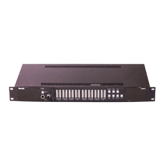
- Page 1 Marshall Electronics AR-DM1-B Digital Audio Monitor with 10-Segment LED Bar Graphs Operating Instructions...
-
Page 2: Table Of Contents
ARDM-AES-4OUT ..................................14 ARDM-AA-2OUT..................................... 14 DOLBY Module ....................................14 ARDM-D552 ....................................14 Module Installation................................15 Input / Output Module Installation ..............................15 DOLBY Module Installation................................16 Specifications ..................................18 AR-DM1-B Audio Monitor................................18 Input / Output Modules ..................................19 Warranty....................................20... -
Page 3: Product Overview
Interchangeable input and output modules provide unrivaled flexibility – up to four I/O modules can be installed in a single AR-DM1-B audio monitor, each module with up to 16 channel inputs, providing a possible 64 channels per audio monitor. Input choices include balanced/unbalanced AES/EBU, SDI video with ®... -
Page 4: Installation And Initial Setup
The AR-DM1-B audio monitor can be installed in an EIA-standard 19-inch rack. At only 7.8” inches deep, the AR-DM1-B can also be installed in many shallow racks cases. Alternately, the AR-DM1-B audio monitor can be placed on any level surface. For optimum sound quality, the audio monitor should be installed at ear level. -
Page 5: Quick Start Guide
Quick Start Guide Install an Input Module Ensure at least one input module is installed in the AR-DM1-B audio monitor. If no modules are installed, see Module Installation (page 15) for detailed instructions. Connect an Audio Source Connect an audio source to the audio monitor. Depending on the chosen input module, the signal could be SDI video with embedded audio, AES/EBU digital audio, analog audio, etc. -
Page 6: Front Panel Features
Front Panel Features Stereo Loudspeakers Channel-Assign and DOLBY Indicator LEDs The stereo loudspeakers are active unless The channel assign LED below each bar graph headphones are connected. indicates how that channel is being reproduced through the stereo speakers (see page 9). The Power Indication LED DOLBY LED below each channel pair indicates the The power LED will illuminate green when power is... -
Page 7: Rear Panel Features
Power Input Connector Use only the included power supply to power the AR-DM1-B audio monitor. RS-485 Port The RS-485 port is used to download firmware to the AR-DM1-B audio monitor. Contact Marshall Electronics regarding available firmware upgrades and instructions. I/O Module Slots... -
Page 8: Basic Operation
Overview Basic operation of the AR-DM1-B Audio Monitor involves selecting an input module as the audio source, using the LED bar graphs to visually monitor signal levels, and choosing a mode in which to monitor audio through the stereo speakers. -
Page 9: Audio Monitoring
Basic Operation (continued) Audio Monitoring ■ Monitor Modes Audio channels from the selected input module can be monitored through the stereo speakers in three ways: one channel at a time (mono), two channels at a time (stereo), or as a stereo mix of multiple channels (5.1, 7.1, etc.). Single Mode Press the SINGLE button to monitor one channel at a time. -
Page 10: Headphone Output And Audio Adjustments
Basic Operation (continued) Headphone Output and Audio Adjustments ■ Headphone Output The headphone output accepts standard stereo headphones with a 1/4" TRS connector. Headphones with an 1/8” (3.5mm) mini-plug connector may be used with an adapter. The stereo speakers are muted when a connector is plugged into the headphone output. -
Page 11: Dolby Encoded Signals
The ARDM-552 DOLBY Module must be installed in the AR-DM1-B audio monitor in order to decode DOLBY signals from any input module. If this module is not present, the AR-DM1-B will indicate DOLBY signal presence with the aforementioned blue LED, but will not be able to decode the bitstream into discrete channels. -
Page 12: Dolby Downmix Configurations
DOLBY Decoding (continued) DOLBY Downmix Configurations The following table shows the available downmix configurations and corresponding channel assignments for common DOLBY E program configurations (PGM) and DOLBY DIGITAL audio coding modes (ACM). Channel Assignments DOLBY Type PGM / ACM Available Presets Ch. -
Page 13: Optional Modules
Optional Modules Input Modules ■ ARDM-AES-BNC ■ ARDM-HDSDI Features: Features: • 4 Unbalanced AES/EBU Inputs (8 Audio Channel Inputs) • HD-SDI Input (16 Audio Channel Inputs) • 4 Passive Loop-Through Outputs (8 Audio Channel Outputs) • Re-Clocked HD-SDI Loop-Through Output •... -
Page 14: Output Modules
Optional Modules (continued) Output Modules ■ ARDM-AES-4OUT ■ ARDM-AA-2OUT Features: Features: • 4 Unbalanced AES/EBU Outputs (8 Audio Channels Outputs) • 2 Balanced Analog Audio Outputs • Outputs the 8 channels currently selected on the audio monitor • Built-In XLR Connectors •... -
Page 15: Module Installation
Module Installation Input / Output Module Installation The ARDM-series input and output modules are designed for simple installation and removal without tools. Use the following instructions to install a module: 1. Ensure that the audio monitor is powered off. Modules cannot be installed or “hot swapped” while the audio monitor is powered on. -
Page 16: Dolby Module Installation
IMPORTANT: The following procedure involves exposing and handling bare electronic components. Proper anti-static precaution must be taken before opening the AR-DM1-B Audio Monitor to avoid damage during installation. This includes working on a static-free surface and wearing a grounded wrist-strap or another type of grounding device. Opening the AR-DM1-B Audio Monitor without proper anti-static precaution may void the warranty. - Page 17 Do not force the module into place if it does not move easily. 7. To remove the module, push aside the metal brackets on each side of the slot so that the module is release upward. 8. Close the AR-DM1-B Audio Monitor by re-fastening the 14 screws on the top panel.
-
Page 18: Specifications
Specifications AR-DM1-B Audio Monitor ■ METERS Meter Type: 16 x 10 Segment LED Bar Graph Meter Dynamics: Simultaneous VU & PPM (True Peak) Meter Scale: 0 to -66dB ■ ACOUSTIC Speaker Power Output: Left/Right RMS @ 4Ω: 10W, 14W Peak... -
Page 19: Input / Output Modules
Specifications (continued) Input / Output Modules ■ ARDM-HDSDI Input Module Inputs: 1 x SDI (75Ω BNC) – 16 channels embedded audio Outputs: 1 x SDI Equalized Loop-Through (75Ω BNC) SDI Formats: 525i, 625i, 720p, 1080i, 1080p SDI Standards: SMPTE 259M, 292M, 274M, 296M, 260M Audio Coding: PCM, DOLBY E, DOLBY DIGITAL (AC-3) Sample Rates:... -
Page 20: Warranty
This warranty is extended to the first consumer only, and proof of purchase is necessary to honor the warranty. If there is no proof of purchase provided with a warranty claim, Marshall Electronics reserves the right not to honor the warranty set forth above.
Need help?
Do you have a question about the AR-DM1-B and is the answer not in the manual?
Questions and answers