
Related Manuals for West Pond Enterprises MX-400 Series

Summary of Contents for West Pond Enterprises MX-400 Series
- Page 1 MX-400xx Installation & Operations Manual Software Revision 2.0.14 West Pond Enterprises, LLC 11/7/2019...
-
Page 2: Table Of Contents
Contents Revision History ............................3 Related documentation ..........................3 Terms and terminology ..........................3 MX-400 Smart Headend ..........................4 MX-400 Hardware ............................. 7 MX-400 Software ............................7 Setting up the system ........................... 7 Unpacking the unit ............................ 7 Installing ..............................7 Making the connections .......................... - Page 3 Info ..............................23 Tools ..............................24 Appendix A – Quick Start Help ........................25 Appendix B – FAQs ............................27 How do I create a TV channel from a video file? ................27 Confidential Page 2...
-
Page 4: Revision History
Revision History Date Version Description 7/20/2017 1.0.2 Created for version 1.0.2 of the software 11/29/2017 1.10.0 Time to update…. Bring to latest software revision 12/1/2017 1.11.0 Add discovery, add discovery to quick start 5/17/2018 1.16.5 6/3/2018 1.16.6 Fixed FlexDM port typo (should be 1194) 6/28/2019 1.17.3 Included FlexDM sync cloud icon. -
Page 5: Mx-400 Smart Headend
IPTV, and HTML5 multi-media. This document will help you to get your MX-400 up and running quickly. For your convenience a quick start section is provide at the end of this document. See Appendix A – Quick Start Help. For more information please contact West Pond Enterprises sales or support. - Page 6 o Our integrated scalable multiplexer replaces the need for external rack mounted devices. Multi-channel modulator o 1 - 9 multi-channel, frequency and modulation agile modulators. GigE switch o 4 Configurable GigE ports reduce the need for and external managed switch and simplify wiring in a mixed LAN environment.
- Page 7 Sample Configuration Confidential Page 6...
-
Page 8: Mx-400 Hardware
MX-400 Hardware A typical MX-400 unit is equipped with one or more HD video capture modules, broadcast or satellite TV tuners, 32 GBytes of video and HTML5 content storage, 4 GigE ports, one or more agile RF modulators, and an RF monitor tuner. The output can be IPTV or RF via the modulator channels. Multiplexor sources can originate from IPTV, RTSP (cameras), DTV tuners, streamed files, or encoded HDMI/Component/Composite video. -
Page 9: Making The Connections
Making the connections There are four Gigabit Ethernet ports on the back of the MX-400. These are independently configured to support four unique LANs. Configure at least one of them as a management LAN from which you can access the MX-400 Web UI. Others may be used to send/receive IPTV streams, access to cameras (RTSP), or access to other assets used by the MX-400. -
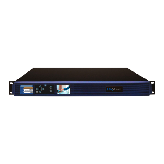
Page 10: Front Panel
Front panel Use the front panel of the MX-400 to check system status, configure each of the MX-400 network ports, and reset the WebUI admin password. The main menu shows the System Name as configured in the Web UI System/Settings page. Use the navigation pad to the right of the left screen to navigate the menus. -
Page 11: Accessing The Webui
Use the CH up/down buttons to the left of the right screen to scroll through the video inputs configured via the Web UI. The video monitoring screen shows a scaled replica of each enabled TS multiplexor input source. Use the up channel and down channel buttons to cycle through the video. This can be done at any time and has no impact on the state of the system. - Page 12 Alternatively you may use the serial number as the URL in your web browser. To access the MX-100 point a web browser at the URL http://yourUnitsSerialNumber.local where yourUnitsSerialNumber is taken from the label on the MX-100. Note: System discovery requires mac OSX, Windows Vista or greater, IOS, or Android device.
-
Page 13: Getting Familiar With The Mx-400
Getting familiar with the MX-400 The West Pond product team may preconfigure your device to provide a head start for your particular application. This may include the installation of template presentations, test videos, and the configuration of input and output streams. The IP addresses used for IP inputs and outputs are likely inappropriate for your installation and may need reconfiguring. -
Page 14: Sources
Sources The Sources page shows how devices and IP streams are enabled as inputs to the multiplexor. Sources may include network streams such as IPTV or an RTSP feed from a security camera the MX-400 internal video server ... -
Page 15: Video Encoder And Html5 Signage System
CableTV QAM modulated output that stream should be MPEG2 (not h.264) encoded so that it is compatible with the ATSC standard and can be used by ATSC TVs. West Pond provides a transcoding web service, FlexDM, which simplifies the process of creating the appropriate files. Visit FlexDM.net for more information. - Page 16 can be encoded with, or without an HTML presentation. Any presentation can be encoded with or without and AV source. There are two tabs on the Video Encoder page: Channels and Presentations. Presentations are simple HTML5 websites stored on the MX-400. Channels are created by the encoders. Your system may have one or more encoders depending upon model and licensing.
- Page 17 The presentations tab also allows you to: Delete a presentation Browse and modify files within a presentation (drag and drop) Create a new presentation by copying an existing presentation Download a presentation to your PC to edit it. (Zip file) Preview a presentation in your browser (sans video and other MX-400 specifics) Configure a presentation using the presentation specific configuration tool Create a new presentation by uploading a Zip file with the appropriate files...
- Page 18 Source Select the AV source, if any, to be used with your channel. No AV source is necessary if the HTML5 presentation is full screen media. Resolution Select the video resolution for your encoded TV channel. Lower resolutions consumer fewer system resources.
-
Page 19: Outputs
Outputs An Output is a multiplexed TS output which exits the MX-400 on a physical transport such as a modulator, ASI port, or Ethernet port. As this is a software multiplexor, there is no specified limit to the number of outputs. From a practical perspective, it’s best to limit the bandwidth consumed by the sum total of all outputs to less than 500... -
Page 20: Modulated Rf Output
A playlist.m3u file that describes all of the multicast outputs can be downloaded by clicking on the playlist icon. For IPTV networks, session announcement protocol (SAP ) is supported and included in the stream when enabled. RFC 2974 RTSP outputs, TS only, are also supported. Modulated RF Output The modulator hardware is automatically detected and a list of available modulators is shown on the Output page of the WebUI. -
Page 21: Fine Tuning The System
appropriately for each program you would like included in this output. Programs included in the transport are highlighted with a green background and a green arrow. On the “Modify program mapping” dialog box, select “Yes” if you wish this source to be included in the output. Be mindful of the bandwidth limitations of your chosen output transport. -
Page 22: Display Controls
primarily consumed by the HTML5 presentations and video server video files. External storage is available from West Pond if your needs exceed the limits of the device. Output Transport Stream If the sum total bit rate for all the programs included the output multiplex is more than the specified maximum bitrate for that transport, clipping will occur to ensure the output does not exceed the maximum bitrate. -
Page 23: Monitor
displayed in the control group dialog. As shown to the right, the power, channel, and volume can be changed in this group. Select the new values and click save. The changes take immediate effect. Monitor The monitor page is used during installation to detect unused frequencies that the modulator output can be configured to use,... -
Page 24: Accounts
NTP: Use the icon to configure the network time server. System Name: Use the icon to set the system name. This name will be displayed on the front panel and on the webUI. Timezone: Use the icon to set the timezone in which the server is being used. This is very important when scheduling playback and other time critical WebUI features. -
Page 25: Tools
Tools These are tools that are used to maintain the system state. System Config: You may export or import the system configuration at any time. This includes account information, the output configuration, and network settings. It does not currently export the provider settings. Use this feature to archive your settings and to clone devices for distribution. -
Page 26: Appendix A - Quick Start Help
Appendix A – Quick Start Help This section is provided to enable installers with a check list of things to do when installing the system. 1) Mount the device and make all the required connections. Power the system on. For more information follow the instruction above in the section: Setting up the system. - Page 27 To set the MX-400 WebUI password to factory defaults, select “Reset Auth” from the system menu. Use the CH up/down buttons to the left of the right screen to scroll through the video inputs configured via the Web UI. The video monitoring screen shows a scaled replica of each enabled TS multiplexor input source.
-
Page 28: Appendix B - Faqs
c. When creating an RF output, utilize the Monitor page to find unused carrier frequencies. d. When selecting the “Program Mapping” be sure of the following: i. All of the sources selected are compatible with the receiving device. i.e. If ATSC, all of the included program streams should be MPEG2 encoded video. - Page 29 Step 3: Create Video Server Channel Create the Video Server Source Channel by clicking on the “Create Channel” button in the “Channels” tab as shown below. Complete the form and click “Create”. A line for this new channel will appear in the “Channels”...
- Page 30 added more than once. Click “Save” when done. You can also schedule files to playback at a particular time of day. To do this click on the icon. This will display the “Schedule” dialog. Scheduled playback overrides the playlist entry for the period in which it is played.
- Page 31 Back to the Outputs page. Select and then click on the icon for the Source you wish to include in the output. A dialog box will appear. For most installations the default selection is the simplest. Experts may want to change some of the signaling.
Need help?
Do you have a question about the MX-400 Series and is the answer not in the manual?
Questions and answers