Table of Contents
Advertisement
Quick Links
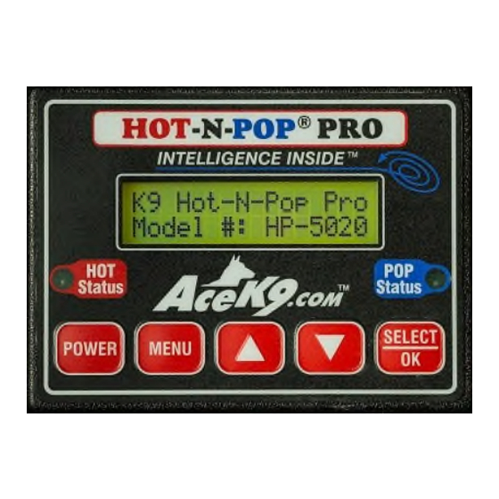
Model HP-5020
Patent # 7,081,811
Hot-N-Pop
Pro
®
With Protective Relay Module
Installation Manual
To be used in conjunction with Vehicle Specific Instructions
Life Safety Equipment
It is vital that all Safety Features are installed, tested and working properly at the
time of installation.
Special Attention needs to be made to Power and Safety Warnings.
This Life Safety Equipment must be installed to Emergency Vehicle Up-fitting
Standards!
Radiotronics Inc.
1315 SW Commerce Way
Stuart Fl 34997
Phone: (772) 600-7574
Fax (772) 600-7012
www.acek9.com
Advertisement
Table of Contents

Summary of Contents for ACEK9 Hot-N-Pop Pro
- Page 1 Special Attention needs to be made to Power and Safety Warnings. This Life Safety Equipment must be installed to Emergency Vehicle Up-fitting Standards! Radiotronics Inc. 1315 SW Commerce Way Stuart Fl 34997 Phone: (772) 600-7574 Fax (772) 600-7012 www.acek9.com...
-
Page 2: Table Of Contents
Contents Warnings and Safety information Page 2 STEP 12 Optional modules Page 9 STEP 1 Installation, Planning Page 3 STEP 13 Heat Alarm Test Page 10 STEP 2 Control Head Page 4 Door Popper Steps STEP 3 IntelaBox Page 4 STEP 14 Neutral safety Page 10... -
Page 3: Warnings And Safety Information
This manual is used in conjunction with the vehicle specific instructions sheet. If the make, model and year do not match the vehicle instructions or the equipment is being reinstalled in new vehicle Contact AceK9.Com Service Department. When contacting AceK9 service, have your SERIAL NUMBER available. ________________________________________________________________________________________... -
Page 4: 1 Installation, Planning
Installation This manual is written to provide the information necessary for safe and reliable operation of Read the Vehicle Specific Instructions this Life Safety Equipment. to guide you thru the install. STEP 1 Planning Consult with the end user • Determine a suitable mounting location for the Control Head. The Head should be easily visible to the K9 Handler. -
Page 5: Control Head
STEP 2 Control Head installation Mount securely in a location that is dry and visible to the K9 handler. Plug the control head cable into the head. STEP 3 Intelabox installation Mount the IntelaBox in a location that allows easy access Find a DRY location where it is easily serviceable for upgrades and programming. -
Page 6: Prm Outputs Chart
Installing K9 Hot-N-Pop ® Pro alert features Connecting outputs from the Protective Relay Module The Protective Relay Module Provides output wires to activate standard horn, lights, and siren activation, and the window drop feature. To accommodate a variety of setups a choice of low current ground triggers or positive activation are provided. -
Page 7: Step 5 Horn Feature
(12+ volts). Connection: Splices into vehicles horn ring wire. 5B For Connection at Horn (+) AceK9 Wire Color: Orange/Yellow and Orange/Red Wires Common on Chrysler, Dodge, and Jeep Vehicles. (See Vehicle Specific Information) Polarity: Orange/Red wire provides positive power to activate the vehicles horn, The Orange/Yellow wire Isolates the power to prevent damaging back feed to the vehicles computer and allows normal activation of the of horn. -
Page 8: 6 Light Feature
Connection: Connect the Green/Red wire to the light side of the switch or controller. (12V+ when triggered Fused at 15A Max) STEP 7 Siren Alert Feature AceK9 Wire Color: (Violet - or Violet/Red +) A Choice of Positive and Negative Outputs are provided. Violet wire provides a negative output (Ground Trigger 3A Max) Violet/Red wire provides a positive output (B+ when triggered Fused at 15A Max) Never connect to wire of emergency vehicles high power siren speaker. -
Page 9: Step 8 Window Drop
STEP 8 Window Drop Feature Refer to Vehicle Specific Instructions for window down wire colors and locations. Using the vehicle specific information as a guide, follow the instructions packed with your window drop module. The Protective Relay Module’s Blue/Red wires supply power to the Window Drop Modules. -
Page 10: Step 10 Ignition Power
Connect any add on accessories purchased with system. See instructions included with accessory. Do not attempt to connect items not approved for use with this system. See the Installation Manual(s) for details. Use only accessories designed for Acek9.com products. Heat Alarm test next page... -
Page 11: Step 13 Heat Alarm Test
Step 13 Test Heat Alarm portion of the System Check your settings, the default hot temperature setting is 90 degrees Fahrenheit. (32 ◦ c), The stall monitor should be enabled only if a stall sensor has installed. Review or change settings from Menu (See the “User Guide”). Test Procedure for K9 Heat Alarm 1) Power the alarm on. -
Page 12: Step 15 Antenna
STEP 15 Door Popper Antenna NOTE: If a combined pager and door popper antenna was purchased, follow the instructions included in the Dual Band Kit. Mount the K9 Door Popper ® antenna by drilling a hole on roof or trunk lid. Mounting Keep Antenna as far away from other antennas as possible. -
Page 13: Unlock Connectionpage
STEP 17 Unlock Connection Unlock Cable color: Blue cable with Yellow and Red wires. See vehicle specific information before proceeding many modern setups require an unlock module For this step see it is important to check your vehicle specific information sheet before you proceed. -
Page 14: Step 20 Solenoid Installation
STEP 20 Solenoid Installation IT IS VITAL THAT ONCE THE SOLENOID IS INSTALLED, THROUGH TESTING BE DONE PRIOR INSTALLING THE DOOR PANELS. Lock Nut Clevis Yoke Ball Chain Coupling Ball Chain Spring Clip + Ball Chain & Coupling Obtain a good view of the door latch mechanism. Locate the cable or lever on the door latch mechanism that if pulled will unlatch the door. -
Page 15: Step 20 Gas Spring
Door Pop Testing. Turn ON the Hot-N-Pop Pro. Verify that the Pop status light is on and not flashing (see Neutral safety information if flashing). Return to the open door with the K9 Door Popper® Remote. Without closing the door, use a tool to simulate the striker. Move tool into the door latch to closed position;... - Page 16 Alternative Mounting...
-
Page 17: Step 21 Finnish And Test
11) Repeat Heat Alarm test (Step 13) If any of these tests fail please check the installation. Contact AceK9.Com Support with the Serial Number, Call 772-600-7574 Be sure K9 handler receives a copy of the User Manual. Acek9.com Two (2) Year Limited Warranty... -
Page 18: Step
Unlock wires connected backwards or shorted. Check 10A Fuse at IntelaBox. Solenoid needs adjustment. Loose or broken electrical connection. Child Lock is on. (772) 600-7574 E-Mail Service@AceK9.com Hours of operation Monday thru Friday 8:00am to 4:30pm EST All rights reserved.AceK9.Com... - Page 19 Hot-N-Pop Pro Protective Relay With Module INSTALL MANUAL...