
Related Manuals for Acer Aspire 5740


Summary of Contents for Acer Aspire 5740
- Page 1 Aspire 5740/5740D/5340 Series Service Guide Service guide files and updates are available on the ACER/CSD web; for more information, please refer to http://csd.acer.com.tw PRINTED IN TAIWAN...
-
Page 2: Revision History
Revision History Please refer to the table below for the updates made on Aspire 5740/5740D/5340 Series service guide. Date Chapter Updates... - Page 3 Copyright Copyright © 2009 by Acer Incorporated. All rights reserved. No part of this publication may be reproduced, transmitted, transcribed, stored in a retrieval system, or translated into any language or computer language, in any form or by any means, electronic, mechanical, magnetic, optical, chemical, manual or otherwise, without the prior written permission of Acer Incorporated.
- Page 4 Conventions The following conventions are used in this manual: SCREEN MESSAGES NOTE WARNING CAUTION IMPORTANT Denotes actual messages that appear on screen. Gives bits and pieces of additional information related to the current topic. Alerts you to any damage that might result from doing or not doing specific actions.
- Page 5 DIFFERENT part number code to those given in the FRU list of this printed Service Guide. You MUST use the list provided by your regional Acer office to order FRU parts for repair and service of customer machines.
-
Page 7: Table Of Contents
Your Acer Notebook tour ........ - Page 8 Aspire 5740/5740D/5340 ........
-
Page 9: System Specifications
• ® Intel Core i3 processor • ® Mobile Intel HM55 Express Chipset • ™ ™ Acer InviLink Nplify 802.11b/g/n* • ™ Acer InviLink 802.11b/g* • System memory Dual-Channel SDRAM support • Up to 4 GB of DDR3 1066 MHz memory, upgradeable to 8 GB using two soDIMM modules •... -
Page 10: Special Keys And Controls
True5.1-channel surround sound output • High-definition audio support • S/PDIF (Sony/Philips Digital Interface) support for digital speakers • MS-Sound compatible • Built-in microphone • Communication Integrated Acer Crystal Eye webcam • WLAN: • ® ® Intel Centrino • ® ®... -
Page 11: Dimension And Weight
DC-in jack for AC adapter • Environment Temperature: • Operating: 5 °C to 35 °C • Non-operating: -20 °C to 65 °C • Humidity (non-condensing): • Operating: 20% to 80% • Non-operating: 20% to 80% • Dimension and weight • Dimensions: 383 (W) x 250 (D) x 26/37 (H) mm (15.1 x 9.9 x 1.03/1.5 inches) •... -
Page 12: System Block Diagram
System Block Diagram Chapter 1... -
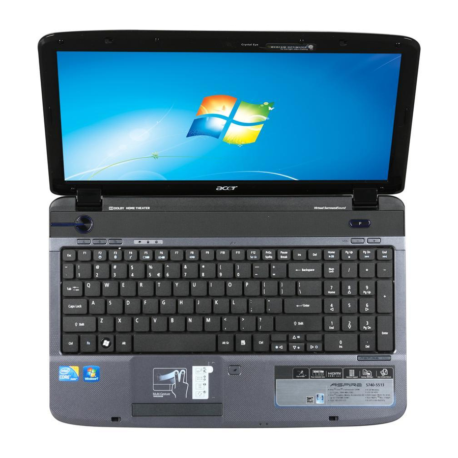
Page 13: Your Acer Notebook Tour
Turns the computer on and off. Enables/disables the wireless LAN function. Indicates the status of wireless LAN communication. Enables/disables the Bluetooth function. Indicates the status of Bluetooth communication Launches Acer Backup Management for three-step data backup. -
Page 14: Closed Front View
Icon Item Num Lock Caps Lock Keyboard Touchpad Click buttons (left and right) Power Battery Palmrest Touchpad toggle Microphone 13 VOL +/- Volume Up/Volume Down 14 P Programmable key Launch user-defined programs at a push of a button. Speakers Closed front view Icon Item Multi-in-1 card... -
Page 15: Rear View
Rear view Item Description Ventilation slots Enable the computer to stay cool, even after prolonged use. Left view Icon Item DC-in jack Ethernet (RJ-45) port HDMI HDMI port External display (VGA) port USB 2.0 ports Line-in jack Microphone-in jack Headphone/speaker/line-out jack with S/PDIF support Chapter 1... -
Page 16: Right View
Right view Icon Item USB 2.0 ports Optical drive Optical disk access indicator Optical drive eject button Emergency eject hole Modem (RJ-11) port Kensington lock slot Description Connect to USB 2.0 devices (e.g., USB mouse, USB camera). Internal optical drive; accepts CDs or DVDs. Lights up when the optical drive is active. -
Page 17: Base View
Base view Icon Item Battery bay Battery release latch Battery lock Hard disk bay Memory compartment Ventilation slots and cooling Chapter 1 Description Houses the computer's battery pack. Releases the battery for removal. Locks the battery in position. Houses the computer's hard disk (secured with screws). Houses the computer's main memory. -
Page 18: Indicators
The mail and Web browser buttons are pre-set to email and Internet programs, but can be reset by users. To set the Web browser, mail and programmable buttons, run the Acer Launch Manager.You can access the Launch Manager by clicking on Start, All Programs, and then Launch Manager to start the application. -
Page 19: Using The Keyboard
Function Left button (2) Execute Quickly click twice. Select Click once. Drag Click and hold, then use finger on the touchpad to drag the cursor. Access context menu NOTE: Illustrations are for reference only. The exact configuration of your PC depends on the model purchased. -
Page 20: Windows Keys
Desired access Main keyboard keys Windows Keys The keyboard has two keys that perform Windows-specific functions. Windows Pressed alone, this key has the same effect as clicking on the Windows Start button; it launches the Start menu. It can also be used with other keys to provide a variety of functions: <... -
Page 21: Hot Keys
Hot Keys The computer employs hotkeys or key combinations to access most of the computer’s controls like screen brightness, volume output and the BIOS utility. To activate hot keys, press and hold the <Fn> key before pressing the other key in the hotkey combination. Hotkey Icon <Fn>... -
Page 22: Hardware Specifications And Configurations
Hardware Specifications and Configurations Processor Item CPU type Aspire 5740: Intel Aspire 5740G: Intel Core logic PCH/HM55 Express chipset CPU package PGA 988 CPU core voltage CPU Fan True Value Table DTS(degree C) Fan Speed (rpm) 45-50 0-3000 55-66 0-3300... - Page 23 Memory Combinations Slot 1 1024MB 1024MB 1024MB 2048MB 2048MB 2048MB NOTE: Above table lists some system memory configurations. You may combine DIMMs with various capacities to form other combinations. On above table, the configuration of slot 1 and slot 2 could be reversed.
- Page 24 Hard Disk Drive Interface Item Vendor & Model 2.5" 5400rpm 160GB Name HGST HTS545016B9A300 WD WD1600BEVT- 22ZCTO Capacity (MB) 160000 Bytes per sector Data heads Drive Format Disks Spindle speed 5400 RPM (RPM) Performance Specifications Buffer size Interface SATA Max. media transfer rate (disk-buffer, Mbytes/s)
- Page 25 Optical Disc Drive Item Applicable disc format Loading mechanism Power Requirement Input Voltage Blu-Ray Disc Drive Item Vendor & model name HLDS BD COMBO DRIVE TRAY DL 4X CT21N LF SONY BD COMBO DRIVE TRAY DL 4X BC-5500H LF PLDS BD COMBO DRIVE TRAY DL 4X DS-4E1S LF Performance With CD Disc Specification...
-
Page 26: Audio Interface
Blu-Ray Disc Drive Item Applicable disc format Applicable disc format CD: CD-DA, CD-ROM, CD-ROM XA, Photo CD (multi-session), Video CD, Cd- Extra (CD+), CD-text DVD: DVD-VIDEO, DVD-ROM, DVD-R (3.9GB, 4.7GB) DVD-R DL, DVD-RW, DVD-RAM, DVD+R, DVD+R DL, DVD+RW CD-DA (Red Book) - Standard Audio CD & CD-TEXT CD-ROM (Yellow Book Mode1 &... - Page 27 Video Item Chipset Memory size System Board Major Chips Item MODEM Bluetooth Wireless 802.11 b/g/n 5 in 1 Card Reader Audio Codec Keyboard Item Keyboard controller Total number of keypads Windows logo key Internal & external keyboard work simultaneously Battery Item Vendor Battery Type...
-
Page 28: System Power Management
LCD 15.6” inches Item Display Mode Typical White Luminance (NIT) also called Brightness Luminance Uniformity Contrast Ratio Response Time msec Nominal Input Voltage VDD Viewing Angle (degree) Horizontal: Right/Left Vertical: Upper/Lower Temperature Range( C) Operating Storage (shipping) AC Adaptor Item Input Output... -
Page 29: System Utilities
System Utilities BIOS Setup Utility The BIOS Setup Utility is a hardware configuration program built into your computer’s BIOS (Basic Input/ Output System). Your computer is already properly configured and optimized, and you do not need to run this utility. However, if you encounter configuration problems, you may need to run Setup. -
Page 30: Navigating The Bios Utility
Navigating the BIOS Utility There are five menu options: Information, Main, Security, Boot, and Exit. Follow these instructions: To choose a menu, use the left and right arrow keys. • To choose an item, use the up and down arrow keys. •... -
Page 31: Information
Information The Information screen displays a summary of your computer hardware information. NOTE: The system information is subject to different models. Parameter CPU Type This field shows the CPU type and speed of the system. CPU Speed This field shows the speed of the CPU. IDE0 Model Name This field shows the model name of HDD installed on primary IDE master. -
Page 32: Main
Main The Main screen allows the user to set the system time and date as well as enable and disable boot menu, SATA mode and recovery. NOTE: The screen above is for your reference only. Actual values may differ. Chapter 2... - Page 33 The table below describes the parameters in this screen. Settings in boldface are the default and suggested parameter settings. Parameter System Time Sets the system time. The hours are displayed with 24-hour format. System Date Sets the system date. System Memory This field reports the memory size of the system.
-
Page 34: Security
Security The Security screen contains parameters that help safeguard and protect your computer from unauthorized use. NOTE: Please refer to “Remove HDD/BIOS Password” section if you need to know how to remove HDD/BIOS Password. The table below describes the parameters in this screen. Settings in boldface are the default and suggested parameter settings. -
Page 35: Removing A Password
Setting a Password Follow these steps as you set the user or the supervisor password: Use the up/down keys to highlight the Set Supervisor Password parameter and press the Enter key. The Set Supervisor Password box appears: Type a password in the “Enter New Password” field. The password length can not exceeds 8 alphanumeric characters (A-Z, a-z, 0-9, not case sensitive). - Page 36 Type the current password in the Enter Current Password field and press Enter. Type a password in the Enter New Password field. Retype the password in the Confirm New Password field. Press e. After setting the password, the computer sets the User Password parameter to “Set”. If desired, you can enable the Password on boot parameter.
-
Page 37: Boot
Boot This menu allows the user to decide the order of boot devices to load the operating system. Bootable devices includes the diskette drive in module bay, the onboard hard disk drive and the CD-ROM in module bay. Chapter 2... -
Page 38: Exit
Exit The Exit screen contains parameters that confirmed or discard the changes made to the parameters in the BIOS Setup Utility. The table below describes the parameters in this screen. Parameter Exit Saving Changes Exit System Setup and save your changes to CMOS. Exit Discarding Changes Exit utility without saving setup data to CMOS. -
Page 39: Bios Flash Utility
BIOS Flash Utility The BIOS flash memory update is required for the following conditions: New versions of system programs • New features or options • Restore a BIOS when it becomes corrupted. • Use the Flash utility to update the system BIOS flash ROM. NOTE: If you do not have a crisis recovery disk at hand, then you should create a Crisis Disk (See “Creating the Crisis Disk in Windows”... -
Page 40: Remove Hdd Password
Remove HDD Password This section teaches you how to remove HDD password: Remove HDD Password: If you key in the wrong HDD password thrice, “HDD password error code” will appear on the • screen. See the image below. If you need to solve HDD password locked problem, you can run HDD_PW.EXE •... -
Page 41: Disassembly Requirements
Machine Disassembly and Replacement This chapter contains step-by-step procedures on how to disassemble the notebook computer for maintenance and troubleshooting. Disassembly Requirements To disassemble the computer, you need the following tools: Wrist grounding strap and conductive mat for preventing electrostatic discharge •... -
Page 42: General Information
General Information Pre-disassembly Instructions Before proceeding with the disassembly procedure, make sure that you do the following: Turn off the power to the system and all peripherals. Unplug the AC adapter and all power and signal cables from the system. Place the system on a flat, stable surface. -
Page 43: External Module Disassembly Process
External Module Disassembly Process External Modules Disassembly Flowchart The flowchart below gives you a graphic representation on the entire disassembly sequence and instructs you on the components that need to be removed during servicing. For example, if you want to remove the main board, you must first remove the keyboard, then disassemble the inside assembly frame in that order. -
Page 44: Removing The Battery Pack
Removing the Battery Pack Turn base unit over. Slide the battery lock/unlock latch to the unlock position. Note: Battery has been highlighted with the yellow circle as above image shows. Please detach the battery and follow the local regulations for disposal. Slide the battery release latch to the release position to pop out the battery pack, then remove the battery pack from the main unit. -
Page 45: Removing The Sd Dummy Card
Removing the SD Dummy Card Push the SD dummy card all the way in to eject it. Pull it out from the slot. Chapter 3... -
Page 46: Removing The Dimm Module
Removing the DIMM Module See “Removing the Battery Pack” on page 36. Remove the one captive screw and one screw (A) securing the DIMM module cover. Size (Quantity) M2.5 x L8 (1) Black Use a plastic screw driver to carefully pry open the DIMM module cover. Color Torque 3 kgf-cm... -
Page 47: Removing The Back Cover
Push out the latches on both sides of the DIMM socket to release the DIMM. Remove the DIMM module. Removing the Back Cover See “Removing the Battery Pack” on page 36. See “Removing the SD Dummy Card” on page 37. See “Removing the DIMM Module”... -
Page 48: Removing The Hard Disk Drive Module
Use a plastic screw driver to carefully pry open the back cover. Remove the back cover from the lower case. Removing the Hard Disk Drive Module See “Removing the Battery Pack” on page 36. See “Removing the SD Dummy Card” on page 37. See “Removing the DIMM Module”... - Page 49 Remove the one screw (F) securing the hard disk drive module. Size (Quantity) M2 x L4 (1) Silver Slide the hard disk drive module away from the connector. Chapter 3 Color Torque 1.6 kgf-cm Part No. 86.9A552.4R0...
- Page 50 Lift the hard disk drive module and remove it from the hard disk drive bay. NOTE: To prevent damage to device, avoid pressing down on it or placing heavy objects on top of it. Remove the two screws (D) securing the hard disk to the bracket and remove the hard disk from the bracket.
-
Page 51: Removing The Wlan Modules
Removing the WLAN Modules See “Removing the Battery Pack” on page 36. See “Removing the SD Dummy Card” on page 37. See “Removing the DIMM Module” on page 38. See “Removing the Back Cover” on page 39. See “Removing the Hard Disk Drive Module” on page 40. Disconnect the black antenna cable from connector #1 and the white antenna cable from connector #2 on the short wireless board module. -
Page 52: Removing The Optical Drive Module
NOTE: When attaching the antenna back to the WLAN board, make sure the cable are arranged properly. Removing the Optical Drive Module See “Removing the Battery Pack” on page 36. See “Removing the SD Dummy Card” on page 37. See “Removing the DIMM Module” on page 38. See “Removing the Back Cover”... - Page 53 Remove the one screw (C) securing the locker bracket and remove the locker bracket from the optical disk drive module. Size (Quantity) Color Torque Part No. M2 x L3 (1) Silver 1.6 kgf-cm 86.9A552.3R0 Chapter 3...
-
Page 54: Main Unit Disassembly Process
Main Unit Disassembly Process Main Unit Disassembly Flowchart F x 1 VOLUME BUTTON BOARD RIGHT BLUETOOTH SPEAKER MODULE MODULE BOARD SCREW X 6 HEATSINK MODULE Screw List Item Screw M2.5 x L8 M2 x L4 M2 x L4 M2.5 x L10 MAIN UNIT DISASSEMBLY MAIN UNIT... -
Page 55: Removing The Middle Cover
Removing the Middle Cover See “Removing the Battery Pack” on page 36. See “Removing the SD Dummy Card” on page 37. See “Removing the DIMM Module” on page 38. See “Removing the Back Cover” on page 39. See “Removing the Hard Disk Drive Module” on page 40. See “Removing the WLAN Modules”... - Page 56 10. Detach the cable from the volume button board on the middle cover. 11. Remove the one screw (F) from the volume button board and release the volume button board from the latch. Size (Quantity) M2 x L4 (1) Silver Color Torque 1.6 kgf-cm...
-
Page 57: Removing The Keyboard
12. Detach the volume button board from the middle cover. Removing the Keyboard See “Removing the Battery Pack” on page 36. See “Removing the SD Dummy Card” on page 37. See “Removing the DIMM Module” on page 38. See “Removing the Back Cover” on page 39. See “Removing the Hard Disk Drive Module”... -
Page 58: Removing The Lcd Module
10. Disconnect the keyboard cable from the main board and detach the keyboard. Removing the LCD Module See “Removing the Battery Pack” on page 36. See “Removing the SD Dummy Card” on page 37. See “Removing the DIMM Module” on page 38. See “Removing the Back Cover”... - Page 59 10. Release the cables from the latches. 11. Carefully pull out the wireless antenna cables from the hole(s). 12. Release the cables from the latches. Chapter 3...
- Page 60 13. Turn over the system and remove the two screws (A) from the bottom of the left and right hinges. Size (Quantity) Color Torque Part No. M2.5 x L8 (2) Black 3.0 kgf-cm 86.00E34.738 14. Detach the LCD cable from the connector on the main board. Chapter 3...
-
Page 61: Separating The Upper Case From The Lower Case
15. Remove the two screws (G) from the left and right hinge of the LCD module. Size (Quantity) M2.5 x L10 (2) Silver 16. Carefully remove the LCD module from the base unit. NOTE: When connecting the cable back to the unit, please note that the cable should be routed well. Separating the Upper Case from the Lower Case See “Removing the Battery Pack”... - Page 62 11. Remove the three screws (F) from the middle cover. Size (Quantity) Color Torque Part No. M2 x L4 (3) Silver 1.6 kgf-cm 86.9A552.4R0 12. Release the latch and disconnect the volume button board cable from its connector the main board. 13.
- Page 63 14. Release the latch and disconnect the touchpad button cable from FPCN1 connector on the main board. 15. Disconnect the speaker cable from its connector on the main board. 16. Disconnect the microphone connector from the main board and remove the microphone. Chapter 3...
- Page 64 17. Remove the ten screws (A) securing the lower case to the upper case. Size (Quantity) Color Torque Part No. M2.5 x L8 (10) Black 3.0 kgf-cm 86.00E34.738 18. Gently detach the upper case from the lower case. 19. Remove the upper case. Chapter 3...
-
Page 65: Removing The Touchpad And Touchpad Button Boards
Removing the Touchpad and Touchpad Button Boards See “Removing the Battery Pack” on page 36. See “Removing the SD Dummy Card” on page 37. See “Removing the DIMM Module” on page 38. See “Removing the Back Cover” on page 39. See “Removing the Hard Disk Drive Module”... - Page 66 14. Release the touchpad button board metal bracket from the latches and detach it from the upper case. 15. Release the touchpad button board from the latches and detach it from the upper case. Chapter 3...
- Page 67 16. Pry to loosen the touchpad board. WARNING: The touchpad board is glued to the upper case, only remove the touchpad board if it is defective. Note: Circuit board >10 cm² has been highlighted with the yellow rectangle as above image shows. Please detach the Circuit boards and follow local regulations for disposal.
-
Page 68: Removing The Left Speaker Module
17. Detach the touchpad board from the upper case. Note: Circuit boards > 10cm above. Please detach the circuit boards and follow the local regulations for disposal. Removing the Left Speaker Module See “Removing the Battery Pack” on page 36. See “Removing the SD Dummy Card”... -
Page 69: Removing The Usb Board Module
12. Remove the two screws (E) securing the left speaker module and remove it from the upper case. Size (Quantity) M2 x L4 (2) Black 13. Detach the left speaker module. Removing the USB Board Module See “Removing the Battery Pack” on page 36. See “Removing the SD Dummy Card”... - Page 70 12. Disconnect the cables from the USB board module. 13. Remove the one screw (F) securing the USB board module to the lower case. Size (Quantity) Color Torque Part No. M2 x L4 (1) Silver 1.6 kgf-cm 86.9A552.4R0 Chapter 3...
-
Page 71: Removing The Modem Module
14. Remove the USB board module from the lower case. Removing the Modem Module See “Removing the Battery Pack” on page 36. See “Removing the SD Dummy Card” on page 37. See “Removing the DIMM Module” on page 38. See “Removing the Back Cover” on page 39. See “Removing the Hard Disk Drive Module”... -
Page 72: Removing The Bluetooth Module
15. Remove the one screws (F) securing the modem board module to the lower case. Size (Quantity) M2 x L4 (1) Silver 16. Release the modem board module from the latch and remove it from the lower case. Removing the Bluetooth Module See “Removing the Battery Pack”... -
Page 73: Remove The Bluetooth Module
11. See “Separating the Upper Case from the Lower Case” on page 53. 12. See “Removing the Left Speaker Module” on page 60. 13. See “Removing the USB Board Module” on page 61. 14. See “Removing the Modem Module” on page 63. 15. -
Page 74: Removing The Right Speaker Module
Removing the Right Speaker Module See “Removing the Battery Pack” on page 36. See “Removing the SD Dummy Card” on page 37. See “Removing the DIMM Module” on page 38. See “Removing the Back Cover” on page 39. See “Removing the Hard Disk Drive Module” on page 40. See “Remove the two screws (D) securing the hard disk to the bracket and remove the hard disk from the bracket.”... - Page 75 17. Disconnect the speaker cable from its connector on the main board. 18. Remove the one screw (E) securing the speaker module and remove it from the lower case. Size (Quantity) Color Torque Part No. M2 x L4 (1) Black 1.6 kgf-cm 86.00E13.524 Chapter 3...
-
Page 76: Removing The Main Board
19. Detach the right speaker module. Removing the Main Board See “Removing the Battery Pack” on page 36. See “Removing the SD Dummy Card” on page 37. See “Removing the DIMM Module” on page 38. See “Removing the Back Cover” on page 39. See “Removing the Hard Disk Drive Module”... - Page 77 17. Remove one screw (F) securing the main board in place. Size (Quantity) Color Torque Part No. M2 x L4 (1) Silver 1.6 kgf-cm 86.9A552.4R0 Note: RTC battery has been highlighted with the yellow circle as shown in the figure above. Please detach the RTC battery and follow local regulations for disposal.
-
Page 78: Removing The Heatsink Module
19. Carefully remove the main board. Removing the Heatsink Module NOTE: There are two version of heatsink module. For this section, we are going to use the discrete model. The UMA version looks like the picture below: See “Removing the Battery Pack” on page 36. See “Removing the SD Dummy Card”... - Page 79 17. See “Removing the Main Board” on page 68. 18. Disconnect the heatsink connector from the main board. 19. Remove the seven screws securing the heatsink module in the order shown. NOTE: The Discrete system may be shipped with AMD PARK_XT or AMD MADISON_PRO. Chapter 3...
-
Page 80: Removing The Cpu
20. Carefully lift up the heatsink module. Removing the CPU See “Removing the Battery Pack” on page 36. See “Removing the SD Dummy Card” on page 37. See “Removing the DIMM Module” on page 38. See “Removing the Back Cover” on page 39. See “Removing the Hard Disk Drive Module”... - Page 81 19. Using a flat screwdriver, turn the CPU socket latch counter-clockwise to release the CPU. 20. Lift up carefully to remove the CPU. NOTE: When installing the CPU, make sure to install the CPU with PIN 1 at the corner as shown. Chapter 3...
-
Page 82: Lcd Module Disassembly Process
LCD Module Disassembly Process LCD Module Disassembly Flowchart LCD ASSEMBLY LCD FPC LEFT LCD CABLE BRACKET Screw List Item Screw M2.5 x L6 M2 x L3 LCD MODULE DISASSEMBLY LCD MODULE LCD BEZEL RIGHT LCD BRACKET ANTENNAS Color Black Silver LCD BACK PANEL CAMERA Part No. -
Page 83: Removing The Lcd Bezel
Removing the LCD Bezel See “Removing the Battery Pack” on page 36. See “Removing the SD Dummy Card” on page 37. See “Removing the DIMM Module” on page 38. See “Removing the Back Cover” on page 39. See “Removing the Hard Disk Drive Module” on page 40. See “Removing the WLAN Modules”... -
Page 84: Removing The Lcd Panel With The Brackets
13. Carefully pry open the LCD bezel and remove it from the LCD panel. Removing the LCD panel with the Brackets See “Removing the Battery Pack” on page 36. See “Removing the SD Dummy Card” on page 37. See “Removing the DIMM Module” on page 38. See “Removing the Back Cover”... - Page 85 13. Disconnect the cable from the web camera. 14. Remove the four screws (B) securing the LCD assembly. Size (Quantity) Color Torque Part No. M2.5 x L6 (4) Black 3.0 kgf-cm 86.00E12.536 Chapter 3...
-
Page 86: Removing The Lcd Brackets
15. Remove the LCD with the brackets from the back cover. Removing the LCD Brackets See “Removing the Battery Pack” on page 36. See “Removing the SD Dummy Card” on page 37. See “Removing the DIMM Module” on page 38. See “Removing the Back Cover”... -
Page 87: Removing The Fpc Cable
Removing the FPC Cable See “Removing the Battery Pack” on page 36. See “Removing the SD Dummy Card” on page 37. See “Removing the DIMM Module” on page 38. See “Removing the Back Cover” on page 39. See “Removing the Hard Disk Drive Module” on page 40. See “Removing the WLAN Modules”... -
Page 88: Removing The Antennas
16. Disconnect the FPC cable from the LCD panel. Removing the Antennas See “Removing the Battery Pack” on page 36. See “Removing the SD Dummy Card” on page 37. See “Removing the DIMM Module” on page 38. See “Removing the Back Cover” on page 39. See “Removing the Hard Disk Drive Module”... - Page 89 14. See “Removing the LCD Brackets” on page 78. 15. See “Removing the FPC Cable” on page 79. 16. Release the antenna cables from the aluminium tapes. 17. Remove the left and right antenna cables together with the tapes holding them in place. NOTE: There is no need to remove the antenna unless you really need to replace it.
-
Page 90: Removing The Web Camera
Removing the Web Camera See “Removing the Battery Pack” on page 36. See “Removing the SD Dummy Card” on page 37. See “Removing the DIMM Module” on page 38. See “Removing the Back Cover” on page 39. See “Removing the Hard Disk Drive Module” on page 40. See “Removing the WLAN Modules”... -
Page 91: Troubleshooting
Troubleshooting Use the following procedure as a guide for computer problems. NOTE: The diagnostic tests are intended to test only Acer products. Non-Acer products, prototype cards, or modified options can give false errors and invalid system responses. Obtain the failing symptoms in as much detail as possible. -
Page 92: System Check Procedures
System Check Procedures External Diskette Drive Check Do the following to isolate the problem to a controller, driver, or diskette. A write-enabled, diagnostic diskette is required. NOTE: Make sure that the diskette does not have more than one label attached to it. Multiple labels can cause damage to the drive or cause the drive to fail. -
Page 93: Memory Check
External keyboard • If any of these devices do not work, reconnect the cable connector and repeat the failing operation. Memory Check Memory errors might stop system operations, show error messages on the screen, or hang the system. Boot from the diagnostics diskette and start the diagnostic program (please refer to main board. Go to the diagnostic memory in the test items. -
Page 94: Check The Battery Pack
Check the Battery Pack To check the battery pack, do the following: From Software: Check out the Power Management in control Panel In Power Meter, confirm that if the parameters shown in the screen for Current Power Source and Total Battery Power Remaining are correct. -
Page 95: Index Of Error Messages
Index of Error Messages Error Code List Error Codes <No error code> <No error code> Error Message List Error Messages Failure Fixed Disk Stuck Key Keyboard error Keyboard Controller Failed Keyboard locked - Unlock key switch Monitor type does not match CMOS - Run Setup Shadow RAM Failed at offset: nnnn System RAM Failed at offset: nnnn... - Page 96 Error Message List Error Messages System timer error Real time clock error Previous boot incomplete - Default configuration used Memory size found by POST differed from CMOS Diskette drive A error Incorrect Drive A type - run SETUP System cache error - Cache disabled CPU ID: DMA Test Failed Software NMI Failed...
- Page 97 Error Message List No beep Error Messages No beep, power-on indicator turns off and LCD is blank. No beep, power-on indicator turns on and LCD is blank. No beep, power-on indicator turns on and LCD is blank. But you can see POST on an external CRT.
-
Page 98: Phoenix Bios Beep Codes
Phoenix BIOS Beep Codes Code Beeps Verify Real Mode Disable Non-Maskable Interrupt (NMI) Get CPU type Initialize system hardware Initialize chipset with initial POST values Set IN POST flag Initialize CPU registers Enable CPU cache Initialize caches to initial POST values Initialize I/O component Initialize the local bus IDE Initialize Power Management... - Page 99 Code Chapter 4 Beeps Advanced configuration of chipset registers Load alternate registers with CMOS values Initialize interrupt vectors POST device initialization 2-1-2-3 Check ROM copyright notice Check video configuration against CMOS Initialize PCI bus and devices Initialize all video adapters in system QuietBoot start (optional) Shadow video BIOS ROM Display BIOS copyright notice...
- Page 100 Code Beeps Detect and install external RS232 ports Configure non-MCD IDE controllers Detect and install external parallel ports Initialize PC-compatible PnP ISA devices Re-initialize onboard I/O ports Configure Motherboard Configurable Devices (optional) Initialize BIOS Area Enable Non-Maskable Interrupts (NMIs) Initialize Extended BIOS Data Area Test and initialize PS/2 mouse Initialize floppy controller Determine number of ATA drives...
- Page 101 Code Code Chapter 4 Beeps Prepare Boot Initialize DMI parameters Initialize PnP Option ROMs Clear parity checkers Display MultiBoot menu Clear screen (optional) Check virus and backup reminders Try to boot with INT 19 Initialize POST Error Manager (PEM) Initialize error logging Initialize error display function Initialize system error handler PnPnd dual CMOS (optional)
- Page 102 Code Beeps Boot to Mini DOS Clear Huge Segment Boot to Full DOS Chapter 4...
-
Page 103: Index Of Symptom-To-Fru Error Message
Index of Symptom-to-FRU Error Message LCD-Related Symptoms Symptom / Error LCD backlight doesn't work LCD is too dark LCD brightness cannot be adjusted LCD contrast cannot be adjusted Unreadable LCD screen Missing pels in characters Abnormal screen Wrong color displayed LCD has extra horizontal or vertical lines displayed. - Page 104 Power-Related Symptoms Symptom / Error The system doesn’t power-off. Battery can’t be charged PCMCIA-Related Symptoms Symptom / Error System cannot detect the PC Card (PCMCIA) PCMCIA slot pin is damaged. Memory-Related Symptoms Symptom / Error Memory count (size) appears different from actual size.
- Page 105 Power Management-Related Symptoms Symptom / Error The system doesn't resume from hibernation mode. The system doesn't resume from standby mode after opening the LCD. Battery fuel gauge in Windows doesn’t go higher than 90%. System hangs intermittently. Peripheral-Related Symptoms Symptom / Error System configuration does not match the installed devices.
- Page 106 Modem-Related Symptoms Symptom / Error Internal modem does not work correctly. NOTE: If you cannot find a symptom or an error in this list and the problem remains, see “Undetermined Problems” on page 100. Action in Sequence Modem phone port modem combo board System board Chapter 4...
-
Page 107: Intermittent Problems
Intermittent Problems Intermittent system hang problems can be caused by a variety of reasons that have nothing to do with a hardware defect, such as: cosmic radiation, electrostatic discharge, or software errors. FRU replacement should be considered only when a recurring problem exists. When analyzing an intermittent problem, do the following: Run the advanced diagnostic test for the system board in loop mode at least 10 times. -
Page 108: Undetermined Problems
System Check” on page 85.): Power-off the computer. Visually check them for damage. If any problems are found, replace the FRU. Remove or disconnect all of the following devices: Non-Acer devices • Printer, mouse, and other external devices • Battery pack •... -
Page 109: Connector Locations
Connector Locations Main Board Top View Code SPKR_L1 Left speaker cable connector Keyboard cable connector AMIC1 MIC cable connector SPKR_R1 Right speaker cable connector PSCN1 Volume button board cable connector TPCN1 Touchpad board cable connector FPCN1 Fingerprint cable connector RTC1 RTC battery connector USBCN1 USB cable connector... -
Page 110: Bottom View
Bottom View Code LOUT1 MICIN1 LIN1 USB1 & USB3 CRT1 FAN1 HDMI1 RJ45 DCIN1 CPU1 Connector Bluetooth board cable connector Headphone/speaker/line-out jack Microphone-in jack Line-in port USB 2.0 ports VGA port Heatsink fan cable connector HDMI port Ethernet port DC-in port CPU socket Chapter 5... -
Page 111: Clearing Password Check And Bios Recovery
Hardware Open Gap Description Hardware Hardware Gap Position on the Main Board Gap name in Aspire 5740/5740D/5340 Series is G77. Steps for Clearing BIOS Password Check If the user sets the BIOS Password (Supervisor Password and/or User Password) for a security reason, the BIOS will ask for the password during system POST or when the system enters into the BIOS Setup menu. -
Page 112: Bios Recovery By Crisis Disk
• If there is no password request, the BIOS Password is cleared. Otherwise, repeat the steps above and try again. NOTE: The steps are only for clearing the BIOS password (Supervisor Password and User Password). BIOS Recovery by Crisis Disk BIOS Recovery Boot Block BIOS Recovery Boot Block is a special block of the BIOS. - Page 113 Decompress the Crisis Package Source. Select WINCRIS.EXE and then select Run as administrator under Windows. Keep the default settings and then click on the Start button. When the pop-up warning dialog box appears, press OK to continue creating the Crisis Disk. Chapter 5...
- Page 114 The Crisis Disk will be created after a few seconds. Press No if you do not want to create another Crisis Disk. Chapter 5...
- Page 115 Reconnect the USB removable storage device and check if it contains the 3 files shown in the following figure. Chapter 5...
- Page 116 Chapter 5...
-
Page 117: Fru (Field Replaceable Unit) List
DIFFERENT part number code from those given in the FRU list of this printed Service Guide. You MUST use the local FRU list provided by your regional Acer office to order FRU parts for repair and service of customer machines. -
Page 118: Exploded Diagram
Exploded Diagram Chapter 6... -
Page 119: Fru List
FRU List Aspire 5740/5740D/5340 Series FRU List 1. ACER_ASPIRE 5740 UMACBB_JV50_CP (NO: LX.PM902.064/88 ) Category ADAPTER BATTERY BOARDS Chapter 6 Part Name and Description ADAPTER 65W 19V 3PIN DELTA ADP-65JH DB A LV5 LED LF YELLOW ADAPTER 65W 19V 3PIN LITEON PA-1650-22AC LV5 LED LF... - Page 120 POWER CORD 7A 125V 2PIN JAPAN BK POWER CORD 250V 10A 3PIN ISRAEL POWER CORD 2.5A 125V USA POWER CORD 2.5A 125V 1.8M BLACK TAIWANESE POWER CORD 10A 250V 1.8M BRAZIL BLK POWER CORD ACA / ACNZ Acer Part No. NI.23600.062 NI.23600.064 NI.23600.066 50.PAW01.004 50.PAW01.003 50.4CG02.001...
- Page 121 LCD BEZEL 15.6" W/CAMERA HOLE FOR JAPAN LCD BEZEL 15.6" W/CAMERA HOLE LCD COVER IMR 15.6" BLUE W/ANTENNA*2 & LOGO FOR HMW 60.PEZ01.001 LED LCD BRACKET RIGHT W/HINGE LED LCD BRACKET LEFT W/HINGE LOWER CASE W/MODEM CABLE&SPEAKER Acer Part No. 27.03218.051 27.03518.161 50.PAW01.001 50.PAW01.001 50.PAW01.002 50.PAW01.002...
- Page 122 CPU INTEL CORE I5 520M 2.4G 35W ARRANDALE 3M CPU INTEL CORE I7 620M PGA 2.66G ARRANDALE 4M DVD-RW SUPER-MULTI MODULE 8X SATA (FOR WINDOWS7) ODD TOSHIBA SUPER-MULTI DRIVE 12.7MM TRAY DL 8X TS- L633C LF W/O BEZEL SATA FOR HF+WINDOWS7 Acer Part No. 42.PAW01.001 33.PAW01.002 42.TKJ01.001 33.PAW01.001 42.PAW01.002...
- Page 123 KEYBOARD 103KEYS NSK-ALA0J AC7T JV50 INTERNAL 17 STANDARD BLACK TEXTURE TAIWAN KEYBOARD 103KEYS NSK-ALA0J AC7T JV50 INTERNAL 17 STANDARD BLACK TEXTURE THAILAND KEYBOARD 104KEYS NSK-ALA0J AC7T JV50 INTERNAL 17 STANDARD BLACK TEXTURE PORTUGAL Acer Part No. KU.00807.070 KU.0080D.048 KU.0080E.027 KU.0080F.006 KH.16007.024 KH.16008.022...
- Page 124 LED LCD 15.6"W WXGA GLARE SAMSUNG LTN156AT02-A02 LF 220NIT 8MS 500:1 LED LCD 15.6" WXGA GLARE LG LP156WH2-TLE1 LF 220NIT 8MS 400:1 LED LCD CMO 15.6" W WXGA GLARE N156B6-L06 LF 220NIT 8MS 500:1 Acer Part No. KB.I170A.047 KB.I170A.032 KB.I170A.037 KB.I170A.043 KB.I170A.039 KB.I170A.057...
- Page 125 SCREW M2.5XL6 H=0.7~0.8MM SCREW M2XL4 SCREW M2.5XL8 NYLOK CR3+ SCREW M2.5XL10 SCREW M2XL3 SCREW M2XL4 WAFER NI SCREW MACH WAFER M3XL4 NI SPEAKER ON LOWER CASE SPEAKER ON UPPER CASE Acer Part No. MB.PM601.00 KN.1GB07.001 KN.1GB09.012 KN.1GB0B.028 KN.1GB0G.025 KN.2GB0B.012 KN.2GB07.001 KN.2GB09.006 KN.2GB0G.014...
-
Page 126: Model Definition And Configuration
Appendix A Model Definition and Configuration Appendix A... -
Page 127: Aspire 5740/5740D/5340
Aspire 5740/5740D/5340 NOTE: All models have following common specifications: aard reader (5-in-1), wireless LAN (3rd WiFi 2x2 BGN), NB chipset (HM55), battery (6CELL2.2), Model Country Acer Part No Description AS5740DG-434G50Mn EM W7HP64EMATME9 MC AS5740DG- EMEA Middle East LX.PRF02.035 MADISON_PRO1GBCbb_V3 2*2G/500_L/ 434G50Mn 6L2.2/5R/... - Page 128 AS5740DG-434G50Mn EM W7HP64EMATZA4 MC AS5740DG- EMEA South Africa LX.PRF02.028 MADISON_PRO1GBCbb_V3 2*2G/500_L/ 434G50Mn 6L2.2/5R/ CB_3D_GN_0.3D_GC_GWW_HG_ES61 AS5740DG-334G32Mn EM W7HP64EMATZA2 MC AS5740DG- EMEA South Africa LX.PRF02.045 MADISON_PRO1GBCbb_V3 2*2G/320/ 334G32Mn 6L2.2/5R/ CB_3D_GN_0.3D_GC_GWW_HG_ES61 AS5740DG-434G50Mn EM W7HP64EMATZA2 MC AS5740DG- EMEA South Africa LX.PRF02.038 MADISON_PRO1GBCbb_V3 2*2G/500_L/ 434G50Mn 6L2.2/5R/ CB_3D_GN_0.3D_GC_GWW_HG_ES61 AS5740DG-434G50Mn W7HP64ATIL1 MC...
- Page 129 AS5740DG-434G64Mn W7HP64ATSE1 MC AS5740DG- MADISON_PRO1GBCbb_V3 2*2G/640/ EMEA Sweden LX.PRF02.043 434G64Mn 6L2.2/5R/ CB_3D_GN_0.3D_GC_GWW_HG_FI12 AS5740DG-434G50Mn W7HP64ATBE1 MC AS5740DG- MADISON_PRO1GBCbb_V3 2*2G/500_L/ EMEA Belgium LX.PRF02.026 434G50Mn 6L2.2/5R/ CB_3D_GN_0.3D_GC_GWW_HG_NL11 AS5740DG-334G32Mn EM W7HP64EMATME3 MC AS5740DG- EMEA Middle East LX.PRF02.050 MADISON_PRO1GBCbb_V3 2*2G/320/ 334G32Mn 6L2.2/5R/ CB_3D_GN_0.3D_GC_GWW_HG_ES81 AS5740DG-434G50Mn EM W7HP64EMATZA1 MC AS5740DG- EMEA...
- Page 130 AS5740DG-434G50Mn EM W7HP64EMATME2 MC AS5740DG- EMEA Middle East LX.PRF02.031 MADISON_PRO1GBCbb_V3 2*2G/500_L/ 434G50Mn 6L2.2/5R/ CB_3D_GN_0.3D_GC_GWW_HG_AR11 AS5740DG-434G50Mn W7HP64ATCZ2 MC AS5740DG- MADISON_PRO1GBCbb_V3 2*2G/500_L/ EMEA Czech LX.PRF02.016 434G50Mn 6L2.2/5R/ CB_3D_GN_0.3D_GC_GWW_HG_SK11 AS5740DG-434G50Mn W7HP64ATDK2 MC AS5740DG- MADISON_PRO1GBCbb_V3 2*2G/500_L/ EMEA Denmark LX.PRF02.021 434G50Mn 6L2.2/5R/ CB_3D_GN_0.3D_GC_GWW_HG_ENS1 AS5740DG-434G64Mn W7HP64ATDK2 MC AS5740DG- MADISON_PRO1GBCbb_V3 2*2G/640/ EMEA...
- Page 131 AS5740DG-332G32Mn W7HB64SCATCN1 AS5740DG- MC MADISON_PRO1GBCbb_V3 1*2G/320/ CHINA China LX.PRF01.001 332G32Mn 6L2.2/5R/ CB_GN_0.3D_GC_GWE_HG_SC13 AS5740DG-624G64Mn W7HP64ATAU1 MC AS5740DG- Australia/ MADISON_PRO1GBCbb_V3 2*2G/640/BT/ LX.PRF02.088 624G64Mn New Zealand 6L2.2/5R/ CB_GN_0.3D_GC_GWE_HG_ES61 AS5740DG-434G64Mn W7HP64ATFR1 MC AS5740DG- MADISON_PRO1GBCbb_V3 2*2G/640/ EMEA France LX.PRF02.087 434G64Mn 6L2.2/5R/ CB_GN_0.3D_GC_GWW_HG_FR21 AS5740DG-334G32Mn EM W7HP64EMATDZ1 MC AS5740DG- EMEA Algeria...
- Page 132 AS5740DG-334G32Mn W7HP64ATEU7 MC AS5740DG- Eastern MADISON_PRO1GBCbb_V3 2*2G/320/ EMEA LX.PRF02.060 334G32Mn Europe 6L2.2/5R/ CB_GN_0.3D_GC_GWW_HG_SL11 AS5740DG-334G32Mn EM W7HP64EMATME2 MC AS5740DG- EMEA Middle East LX.PRF02.056 MADISON_PRO1GBCbb_V3 2*2G/320/ 334G32Mn 6L2.2/5R/ CB_GN_0.3D_GC_GWW_HG_AR21 AS5740DG-334G32Mn EM W7HP64EMATME2 MC AS5740DG- EMEA Middle East LX.PRF02.051 MADISON_PRO1GBCbb_V3 2*2G/320/ 334G32Mn 6L2.2/5R/ CB_GN_0.3D_GC_GWW_HG_AR11 AS5740DG-334G32Mn EM W7HP64EMATME2 MC...
- Page 133 AS5740DG-334G32Mn W7HP64ATNL1 MC AS5740DG- MADISON_PRO1GBCbb_V3 2*2G/320/ EMEA Holland LX.PRF02.082 334G32Mn 6L2.2/5R/ CB_GN_0.3D_GC_GWW_HG_NL11 AS5740DG-334G32Mn W7HP64ATPL1 MC AS5740DG- MADISON_PRO1GBCbb_V3 2*2G/320/ EMEA Poland LX.PRF02.083 334G32Mn 6L2.2/5R/ CB_GN_0.3D_GC_GWW_HG_PL11 AS5740DG-334G32Mn W7HP64ATLU3 MC AS5740DG- MADISON_PRO1GBCbb_V3 2*2G/320/ EMEA Luxembourg LX.PRF02.079 334G32Mn 6L2.2/5R/ CB_GN_0.3D_GC_GWW_HG_IT41 AS5740DG-334G32Mn W7HP64ATCH1 MC AS5740DG- MADISON_PRO1GBCbb_V3 2*2G/320/ EMEA Switzerland...
- Page 134 AS5740G-434G50Mn EM AS5740G- W7HP64EMATZA2 MC EMEA South Africa LX.PMB02.182 434G50Mn MADISON_PRO1GBCbb_V3 2*2G/500_L/ BT/6L2.2/5R/CB_GN_0.3D_HG_ES61 AS5740G-624G50Mn W7HP64INATIN1 MC AS5740G- India LX.PMB02.181 MADISON_PRO1GBCbb_V3 2*2G/500_L/ 624G50Mn BT/6L2.2/5R/CB_GN_0.3D_HG_ES61 AS5740G-524G50Mn W7HP64INATIN1 MC AS5740G- India LX.PMB02.180 MADISON_PRO1GBCbb_V3 2*2G/500_L/ 524G50Mn BT/6L2.2/5R/CB_GN_0.3D_HG_ES61 AS5740G-524G32Mn W7HP64INATIN1 MC AS5740G- India LX.PMB02.179 MADISON_PRO1GBCbb_V3 2*2G/320/BT/ 524G32Mn 6L2.2/5R/CB_GN_0.3D_HG_ES61 AS5740G-438G50Mn W7HP64INATIN1 MC...
- Page 135 AS5740G-435G50Mn W7HP64ATSG1 MC AS5740G- MADISON_PRO1GBCbb_V3 4G+1G/ Singapore LX.PMB02.164 435G50Mn 500_L/BT/6L2.2/5R/ CB_GN_0.3D_HG_ES61 AS5740G-436G64Mn W7HP64ATSG1 MC AS5740G- Singapore LX.PMB02.162 MADISON_PRO1GBCbb_V3 4G+2G/640/ 436G64Mn BT/6L2.2/5R/CB_GN_0.3D_HG_ES61 AS5740G-336G64Mn W7HP64ATSG1 MC AS5740G- Singapore LX.PMB02.161 MADISON_PRO1GBCbb_V3 4G+2G/640/ 336G64Mn BT/6L2.2/5R/CB_GN_0.3D_HG_ES61 AS5740G-334G64Mn W7HP64ATSG1 MC AS5740G- Singapore LX.PMB02.160 MADISON_PRO1GBCbb_V3 2*2G/640/BT/ 334G64Mn 6L2.2/5R/CB_GN_0.3D_HG_ES61 AS5740G-332G50Mn W7HP64ATSG1 MC AS5740G-...
- Page 136 AS5740G-334G50Mn W7HP64RUATRU1 AS5740G- MC MADISON_PRO1GBCbb_V3 2*2G/ EMEA Russia LX.PMB02.146 334G50Mn 500_L/BT/6L2.2/5R/ CB_GN_0.3D_HG_RU11 AS5740G-544G64Bn W7HP64ATAU1 MC AS5740G- Australia/ LX.PMB02.145 MADISON_PRO1GBCbb_V3 2*2G/640/BT/ 544G64Bn New Zealand 6L2.2/5R/CB_GN_0.3D_HG_ES61 AS5740G-524G64Bn W7HP64ATAU1 MC AS5740G- Australia/ LX.PMB02.144 MADISON_PRO1GBCbb_V3 2*2G/640/BT/ 524G64Bn New Zealand 6L2.2/5R/CB_GN_0.3D_HG_ES61 AS5740G-624G64Bn W7HP64ATAU1 MC AS5740G- Australia/ LX.PMB02.143 MADISON_PRO1GBCbb_V3 2*2G/640/BT/...
- Page 137 AS5740G-434G50Mn EM AS5740G- W7HP64EMATME4 MC EMEA Middle East LX.PMB02.130 434G50Mn MADISON_PRO1GBCbb_V3 2*2G/500_L/ 6L2.2/5R/CB_GN_0.3D_HG_RU61 AS5740G-434G50Mn EM AS5740G- W7HP64EMATME4 MC EMEA Middle East LX.PMB02.122 434G50Mn MADISON_PRO1GBCbb_V3 2*2G/500_L/ 6L2.2/5R/CB_GN_0.3D_HG_ES61 AS5740G-334G64Mn EM AS5740G- W7HP64EMATME4 MC EMEA Middle East LX.PMB02.010 334G64Mn MADISON_PRO1GBCbb_V3 2*2G/640/ 6L2.2/5R/CB_GN_0.3D_HG_ES61 AS5740G-434G50Mn W7HP64ATLV1 MC AS5740G- EMEA Latvia...
- Page 138 AS5740G-434G50Mn W7HP64ATCS1 MC AS5740G- Serbia/ EMEA LX.PMB02.098 MADISON_PRO1GBCbb_V3 2*2G/500_L/ 434G50Mn Macedonia 6L2.2/5R/CB_GN_0.3D_HG_SL11 AS5740G-434G50Mn W7HP64ATEU7 MC AS5740G- Eastern EMEA LX.PMB02.094 MADISON_PRO1GBCbb_V3 2*2G/500_L/ 434G50Mn Europe 6L2.2/5R/CB_GN_0.3D_HG_SL11 AS5740G-434G50Mn W7HP64ATPT1 MC AS5740G- EMEA Portugal LX.PMB02.103 MADISON_PRO1GBCbb_V3 2*2G/500_L/ 434G50Mn 6L2.2/5R/CB_GN_0.3D_HG_PT11 AS5740G-524G50Mn W7HP64ATAU1 MC AS5740G- Australia/ LX.PMB02.134 MADISON_PRO1GBCbb_V3 2*2G/500_L/ 524G50Mn...
- Page 139 AS5740G-334G64Mn EM AS5740G- W7HP64EMATZA4 MC EMEA South Africa LX.PMB02.006 334G64Mn MADISON_PRO1GBCbb_V3 2*2G/640/ 6L2.2/5R/CB_GN_0.3D_HG_ES61 AS5740G-434G50Mn EM AS5740G- W7HP64EMATZA2 MC EMEA South Africa LX.PMB02.128 434G50Mn MADISON_PRO1GBCbb_V3 2*2G/500_L/ 6L2.2/5R/CB_GN_0.3D_HG_ES61 AS5740G-334G64Mn W7HP64ATFR1 MC AS5740G- EMEA France LX.PMB02.056 MADISON_PRO1GBCbb_V3 2*2G/640/ 334G64Mn 6L2.2/5R/CB_GN_0.3D_HG_FR21 AS5740G-334G32Mn W7HP64ATFR1 MC AS5740G- EMEA France...
- Page 140 AS5740G-334G64Mn EM AS5740G- W7HP64EMATME2 MC EMEA Middle East LX.PMB02.009 334G64Mn MADISON_PRO1GBCbb_V3 2*2G/640/ 6L2.2/5R/CB_GN_0.3D_HG_AR11 AS5740G-434G50Mn W7HP64ATCZ2 MC AS5740G- EMEA Czech LX.PMB02.106 MADISON_PRO1GBCbb_V3 2*2G/500_L/ 434G50Mn 6L2.2/5R/CB_GN_0.3D_HG_SK11 AS5740G-334G50Mn W7HP64ATES1 MC AS5740G- EMEA Spain LX.PMB02.061 MADISON_PRO1GBCbb_V3 2*2G/500_L/ 334G50Mn 6L2.2/5R/CB_GN_0.3D_HG_ES51 AS5740G-434G50Mn W7HP64ATHU1 MC AS5740G- EMEA Hungary LX.PMB02.105 MADISON_PRO1GBCbb_V3 2*2G/500_L/...
- Page 141 AS5740G-334G32Mn W7HP64ATGR1 MC AS5740G- EMEA Greece LX.PMB02.089 MADISON_PRO1GBCbb_V3 2*2G/320/ 334G32Mn 6L2.2/5R/CB_GN_0.3D_HG_EL31 AS5740G-336G50Mn W7HP64ATFR1 MC AS5740G- EMEA France LX.PMB02.053 MADISON_PRO1GBCbb_V3 4G+2G/ 336G50Mn 500_L/6L2.2/5R/CB_bgn_0.3D_HG_FR21 AS5740G-524G64Bn W7HP64ATDE1 MC AS5740G- EMEA Germany LX.PMB02.052 MADISON_PRO1GBCbb_V3 2*2G/640/BT/ 524G64Bn 6L2.2/5R/CB_bgn_0.3D_HG_DE11 AS5740G-524G64Mn W7HP64ATDE1 MC AS5740G- EMEA Germany LX.PMB02.051 MADISON_PRO1GBCbb_V3 2*2G/640/ 524G64Mn 6L2.2/5R/CB_bgn_0.3D_HG_DE11...
- Page 142 AS5740G-334G64Mn W7HP64ATLU3 MC AS5740G- EMEA Luxembourg LX.PMB02.038 MADISON_PRO1GBCbb_V3 2*2G/640/ 334G64Mn 6L2.2/5R/CB_bgn_0.3D_HG_IT41 AS5740G-334G64Mn W7HP64ATLV1 MC AS5740G- EMEA Latvia LX.PMB02.037 MADISON_PRO1GBCbb_V3 2*2G/640/ 334G64Mn 6L2.2/5R/CB_bgn_0.3D_HG_RU22 AS5740G-334G64Mn W7HP64ATGB1 MC AS5740G- EMEA LX.PMB02.036 MADISON_PRO1GBCbb_V3 2*2G/640/ 334G64Mn 6L2.2/5R/CB_bgn_0.3D_HG_EN11 AS5740G-334G64Mn W7HP64ATDK2 MC AS5740G- EMEA Denmark LX.PMB02.035 MADISON_PRO1GBCbb_V3 2*2G/640/ 334G64Mn 6L2.2/5R/CB_bgn_0.3D_HG_ENS1 AS5740G-334G64Mn W7HP64ATEU5 MC...
- Page 143 AS5740G-334G64Mn EM AS5740G- W7HP64EMATME4 MC EMEA Middle East LX.PMB02.018 334G64Mn MADISON_PRO1GBCbb_V3 2*2G/640/ 6L2.2/5R/CB_bgn_0.3D_HG_RU61 AS5740G-334G64Mn EM AS5740G- W7HP64EMATDZ1 MC EMEA Algeria LX.PMB02.012 334G64Mn MADISON_PRO1GBCbb_V3 2*2G/640/ 6L2.2/5R/CB_bgn_0.3D_HG_ES81 AS5740G-334G50Mn W7HP64ATES1 MC AS5740G- EMEA Spain LX.PM702.001 MADISON_PRO1GBbb_V3 2*2G/500_L/ 334G50Mn 6L2.2/5R/CB_GN_HG_ES51 AS5740G-436G50Mn W7HP64INATIN1 MC AS5740G- India LX.PMF02.109 PARK_XT512Cbb_V3 4G+2G/500_L/BT/...
- Page 144 AS5740G-352G25Mn EM AS5740G- W7HP64EMATVN1 MC Vietnam LX.PMF02.098 352G25Mn PARK_XT512Cbb_V3 1*2G/250/6L2.2/5R/ CB_GN_0.3D_HG_ES61 AS5740G-354G50Mn LINPUSAVN1 AS5740G- Vietnam LX.PMF0C.015 PARK_XT512Cbb_V3 2*2G/500_L/BT/ 354G50Mn 6L2.2/5R/CB_GN_0.3D_HG_EN11 AS5740G-353G32Mn EM AS5740G- W7HP64EMATVN1 MC Vietnam LX.PMF02.097 353G32Mn PARK_XT512Cbb_V3 2G+1G/320/BT/ 6L2.2/5R/CB_GN_0.3D_HG_ES61 AS5740G-352G25Mn LINPUSAVN1 AS5740G- Vietnam LX.PMF0C.014 PARK_XT512Cbb_V3 1*2G/250/BT/6L2.2/ 352G25Mn 5R/CB_GN_0.3D_HG_EN11 AS5740G-334G50Mn EM AS5740G- W7HP64EMATVN1 MC...
- Page 145 AS5740G-352G25Mn EM AS5740G- W7HP64EMATVN1 MC Vietnam LX.PMF02.089 352G25Mn PARK_XT512Cbb_V3 1*2G/250/BT/6L2.2/ 5R/CB_GN_0.3D_HG_ES61 AS5740G-334G50Mn LINPUSAVN1 AS5740G- Vietnam LX.PMF0C.006 PARK_XT512Cbb_V3 2*2G/500_L/BT/ 334G50Mn 6L2.2/5R/CB_GN_0.3D_HG_EN11 AS5740G-333G32Mn EM AS5740G- W7HP64EMATVN1 MC Vietnam LX.PMF02.088 333G32Mn PARK_XT512Cbb_V3 2G+1G/320/BT/ 6L2.2/5R/CB_GN_0.3D_HG_ES61 AS5740G-333G32Mn LINPUSAVN1 AS5740G- Vietnam LX.PMF0C.005 PARK_XT512Cbb_V3 2G+1G/320/BT/ 333G32Mn 6L2.2/5R/CB_GN_0.3D_HG_EN11 AS5740G-624G64Mn EM AS5740G- W7HP64EMATVN1 MC...
- Page 146 AS5740G-524G50Mn W7HP64ATSG1 MC AS5740G- Singapore LX.PMF02.074 PARK_XT512Cbb_V3 2*2G/500_L/BT/ 524G50Mn 6L2.2/5R/CB_GN_0.3D_HG_ES61 AS5740G-524G64Mn W7HP64ATSG1 MC AS5740G- Singapore LX.PMF02.073 PARK_XT512Cbb_V3 2*2G/640/BT/6L2.2/ 524G64Mn 5R/CB_GN_0.3D_HG_ES61 AS5740G-434G64Mn W7HP64ATSG1 MC AS5740G- Singapore LX.PMF02.072 PARK_XT512Cbb_V3 2*2G/640/BT/6L2.2/ 434G64Mn 5R/CB_GN_0.3D_HG_ES61 AS5740G-434G50Mn W7HP64ATSG1 MC AS5740G- Singapore LX.PMF02.071 PARK_XT512Cbb_V3 2*2G/500_L/BT/ 434G50Mn 6L2.2/5R/CB_GN_0.3D_HG_ES61 AS5740G-334G50Mn W7HP64ATSG1 MC AS5740G- Singapore...
- Page 147 AS5740G-334G32Mn W7HP64ATDE1 MC AS5740G- EMEA Germany LX.PMF02.060 PARK_XT512Cbb_V3 2*2G/320/6L2.2/5R/ 334G32Mn CB_GN_0.3D_HG_DE11 AS5740G-333G32Mn W7HP64ATAT1 MC AS5740G- EMEA Austria LX.PMF02.020 PARK_XT512Cbb_V3 2G+1G/320/6L2.2/ 333G32Mn 5R/CB_GN_0.3D_HG_DE61 AS5740G-333G32Mn W7HP64ATHU1 MC AS5740G- EMEA Hungary LX.PMF02.030 PARK_XT512Cbb_V3 2G+1G/320/6L2.2/ 333G32Mn 5R/CB_GN_0.3D_HG_HU11 AS5740G-333G32Mn W7HP64ATGB1 MC AS5740G- EMEA LX.PMF02.035 PARK_XT512Cbb_V3 2G+1G/320/6L2.2/ 333G32Mn 5R/CB_GN_0.3D_HG_EN11 AS5740G-333G32Mn W7HP64ATCY1 MC...
- Page 148 AS5740G-333G32Mn EM AS5740G- W7HP64EMATTR1 MC EMEA Turkey LX.PMF02.012 333G32Mn PARK_XT512Cbb_V3 2G+1G/320/6L2.2/ 5R/CB_GN_0.3D_HG_TR31 AS5740G-333G32Mn EM AS5740G- W7HP64EMATME2 MC EMEA Middle East LX.PMF02.052 333G32Mn PARK_XT512Cbb_V3 2G+1G/320/6L2.2/ 5R/CB_GN_0.3D_HG_ES61 AS5740G-333G32Mn EM AS5740G- W7HP64EMATME2 MC EMEA Middle East LX.PMF02.050 333G32Mn PARK_XT512Cbb_V3 2G+1G/320/6L2.2/ 5R/CB_GN_0.3D_HG_AR21 AS5740G-333G32Mn EM AS5740G- W7HP64EMATME2 MC EMEA...
- Page 149 AS5740G-524G50Mn W7HP64ATAU1 MC AS5740G- Australia/ LX.PMF02.056 PARK_XT512Cbb_V3 2*2G/500_L/BT/ 524G50Mn New Zealand 6L2.2/5R/CB_GN_0.3D_HG_ES61 AS5740G-434G32Mn W7HP64ATAU1 MC AS5740G- Australia/ LX.PMF02.058 PARK_XT512Cbb_V3 2*2G/320/BT/6L2.2/ 434G32Mn New Zealand 5R/CB_GN_0.3D_HG_ES61 AS5740G-624G32Mn W7HP64SCATCN1 AS5740G- CHINA China LX.PMF02.015 MC PARK_XT512Cbb_V3 2*2G/320/BT/ 624G32Mn 6L2.2/5R/CB_GN_0.3D_HG_SC14 AS5740G-333G32Mn W7HP64ATIL1 MC AS5740G- EMEA Israel LX.PMF02.029 PARK_XT512Cbb_V3 2G+1G/320/6L2.2/...
- Page 150 AS5740G-434G32Mn W7HP64INATIN1 MC AS5740G- India LX.PME02.005 PARK_XT512bb_V3 2*2G/320/BT/6L2.2/ 434G32Mn 5R/CB_GN_HG_ES61 AS5740G-334G32Mn W7HP64INATIN1 MC AS5740G- India LX.PME02.004 PARK_XT512bb_V3 2*2G/320/BT/6L2.2/ 334G32Mn 5R/CB_GN_HG_ES61 AS5740G-434G64Mn W7HP64INATIN1 MC AS5740G- India LX.PME02.003 PARK_XT512bb_V3 2*2G/640/BT/6L2.2/ 434G64Mn 5R/CB_GN_HG_ES61 AS5740G-334G50Mn W7HP64ATPT1 MC AS5740G- EMEA Portugal LX.PME02.001 PARK_XT512bb_V3 2*2G/500_L/6L2.2/5R/ 334G50Mn CB_GN_HG_PT11 AS5740G-524G50Mn W7HP64ATPT1 MC AS5740G-...
- Page 151 AS5740-353G32Mn LINPUSAVN1 UMACbb AS5740- Vietnam LX.PM90C.017 2G+1G/320/6L2.2/5R/ 353G32Mn CB_GN_0.3D_HG_EN11 AS5740-434G50Mn EM W7HP64EMATVN1 AS5740- Vietnam LX.PM902.118 MC UMACbb 2*2G/500_L/BT/6L2.2/5R/ 434G50Mn CB_GN_0.3D_HG_ES61 AS5740-354G50Mn EM W7HP64EMATVN1 AS5740- Vietnam LX.PM902.117 MC UMACbb 2*2G/500_L/6L2.2/5R/ 354G50Mn CB_GN_0.3D_HG_ES61 AS5740-354G50Mn LINPUSAVN1 UMACbb AS5740- Vietnam LX.PM90C.016 2*2G/500_L/6L2.2/5R/ 354G50Mn CB_GN_0.3D_HG_EN11 AS5740-354G50Mn LINPUSAVN1 UMACbb AS5740- Vietnam...
- Page 152 AS5740-435G50Mn W7HP64INATIN1 MC AS5740- India LX.PM902.105 UMACbb 4G+1G/500_L/BT/6L2.2/5R/ 435G50Mn CB_GN_0.3D_HG_ES61 AS5740-434G50Mn LINPUSAIN1 UMACbb AS5740- India LX.PM90C.009 2*2G/500_L/BT/6L2.2/5R/ 434G50Mn CB_GN_0.3D_HG_EN11 AS5740-336G50Mn W7HP64INATIN1 MC AS5740- India LX.PM902.104 UMACbb 2G+4G/500_L/BT/6L2.2/5R/ 336G50Mn CB_GN_0.3D_HG_ES61 AS5740-334G50Mn W7HP64INATIN1 MC AS5740- India LX.PM902.103 UMACbb 2*2G/500_L/BT/6L2.2/5R/ 334G50Mn CB_GN_0.3D_HG_ES61 AS5740-434G50Mn W7HP64INATIN1 MC AS5740- India LX.PM902.102...
- Page 153 AS5740-334G32Mn EM W7HP64EMATME2 AS5740- EMEA Middle East LX.PM902.091 MC UMACbb 2*2G/320/BT/6L2.2/5R/ 334G32Mn CB_GN_0.3D_HG_AR21 AS5740-332G64Mn W7HP64ATAU1 MC AS5740- Australia/ LX.PM902.093 UMACbb 1*2G/640/6L2.2/5R/ 332G64Mn New Zealand CB_GN_0.3D_HG_ES61 AS5740-333G32Mn LINPUSAME2 AS5740- EMEA Middle East LX.PM90C.001 UMACbb 2G+1G/320/BT/6L2.2/5R/ 333G32Mn CB_GN_0.3D_HG_EN13 AS5740-333G25Mn W7HP64RUATRU1 MC AS5740- EMEA Russia LX.PM902.090...
- Page 154 AS5740-334G32Mn W7HP64ATUS1 MC AS5740- LX.PM902.054 UMACbb 2*2G/320/6L2.2/5R/ 334G32Mn CB_GN_0.3D_HG_FRB1 AS5740-354G32Mn W7HP64ATAU1 MC AS5740- Australia/ LX.PM902.066 UMACbb 2*2G/320/6L2.2/5R/ 354G32Mn New Zealand CB_GN_0.3D_HG_ES61 AS5740-624G32Mn W7HP64ATAU1 MC AS5740- Australia/ LX.PM902.065 UMACbb 2*2G/320/6L2.2/5R/ 624G32Mn New Zealand CB_GN_0.3D_HG_ES61 AS5740-544G32Mn W7HP64ATAU1 MC AS5740- Australia/ LX.PM902.064 UMACbb 2*2G/320/6L2.2/5R/ 544G32Mn New Zealand CB_GN_0.3D_HG_ES61...
- Page 155 AS5740-434G50Mn EM W7HP64EMATXC3 AS5740- ACLA- LX.PM902.074 MC UMACbb 2*2G/500_L/6L2.2/5R/ 434G50Mn Portuguese CB_GN_0.3D_HG_EN61 AS5740-333G32Mn EM W7HP64EMATXC3 AS5740- ACLA- LX.PM902.080 MC UMACbb 2G+1G/320/6L2.2/5R/ 333G32Mn Portuguese CB_GN_0.3D_HG_EN61 AS5740-434G50Mn EM W7HP64EMATXC2 AS5740- ACLA- LX.PM902.073 MC UMACbb 2*2G/500_L/6L2.2/5R/ 434G50Mn Portuguese CB_GN_0.3D_HG_XC21 AS5740-333G32Mn EM W7HP64EMATXC2 AS5740- ACLA- LX.PM902.079 MC UMACbb 2G+1G/320/6L2.2/5R/...
- Page 156 AS5740-334G50Mn W7HP64ATPT1 MC AS5740- EMEA Portugal LX.PM902.030 UMACbb 2*2G/500_L/6L2.2/5R/ 334G50Mn CB_bgn_0.3D_HG_PT11 AS5740-334G50Mn W7HP64ATCY1 MC AS5740- EMEA Cyprus LX.PM902.029 UMACbb 2*2G/500_L/6L2.2/5R/ 334G50Mn CB_bgn_0.3D_HG_ES61 AS5740-334G50Mn W7HP64ATCS1 MC AS5740- Serbia/ EMEA LX.PM902.028 UMACbb 2*2G/500_L/6L2.2/5R/ 334G50Mn Macedonia CB_bgn_0.3D_HG_SL11 AS5740-334G50Mn W7HP64ATIT1 MC AS5740- EMEA Italy LX.PM902.027 UMACbb 2*2G/500_L/6L2.2/5R/ 334G50Mn...
- Page 157 AS5740-334G50Mn EM W7HP64EMATME2 AS5740- EMEA Middle East LX.PM902.008 MC UMACbb 2*2G/500_L/6L2.2/5R/ 334G50Mn CB_bgn_0.3D_HG_AR11 AS5740-334G50Mn EM W7HP64EMATME4 AS5740- EMEA Middle East LX.PM902.017 MC UMACbb 2*2G/500_L/6L2.2/5R/ 334G50Mn CB_bgn_0.3D_HG_RU61 AS5740-334G50Mn EM W7HP64EMATDZ1 AS5740- EMEA Algeria LX.PM902.011 MC UMACbb 2*2G/500_L/6L2.2/5R/ 334G50Mn CB_bgn_0.3D_HG_ES81 AS5740-334G50Mn W7HP64RUATUK1 MC AS5740- EMEA Ukraine...
-
Page 159: Test Compatible Components
Appendix B Test Compatible Components This computer’s compatibility is tested and verified by Acer’s internal testing department. All of its system ® functions are tested under compatible Windows operating system for each model. Refer to the following lists for components, adapter cards, and peripherals which have passed these tests. -
Page 160: Hardware Device Tests
USB Speaker(JS1200UA) Dell USB Speaker USB Storage Drive 6 IN 1 Flash Card Reader/Writer Device name Vendor Buffalo Buffalo X Bridge Motorola Logitech Motorola Sony Acer Acer Dell Dell Dell Dell Hawk Dell FarEasTone Chunghwa Telecom Westenhouse Panasonic Huawei... - Page 161 Item Wireless Printer Photosmart C309 (CC35A) All-in-One Printer (4x6 photos/CD/ DVD/Quick Forms)/Scanner/Copier/Fax) Port: USB2.0/Ethernet/PictBridge/802.11g/BT Photosmart C4580 All-in-One Printer (4x6 photos) /Scanner/ Copier Port:USB2.0/802.11g.b/Memory Card Memory Card Multimedia Card RS-MMC 128MB Memory Card RS-MMC Mobile 256MB Memory Card Transcend MMC plus 4GB Card Turbo 200X 2GB MMC Card SD Card 4GB SD PRO Memory Card...
- Page 162 Appendix B...
-
Page 163: Online Support Information
This section describes online technical support services available to help you repair your Acer Systems. If you are a distributor, dealer, ASP or TPM, please refer your technical queries to your local Acer branch office. Acer Branch Offices and Regional Business Units may access our website. However some information sources will require a user i.d. - Page 164 Appendix C...
-
Page 165: Index
AFLASH Utility antennas removing Audio back cover Battery Pack battery power indicator BIOS vendor Version BIOS Recovery BIOS Recovery Boot Block BIOS Recovery by Crisis Disk steps BIOS Recovery Hotkey 21–31 BIOS Utility Navigating Security System Security brightness hotkeys button/indicator bluetooth wireless LAN buttons... - Page 166 LCD bezel removing LCD Brackets removing LCD Module Disassembly Flowchart LCD with the brackets removing Main Main Unit Disassembly Flowchart media access on indicator Memory Check Menu Boot menu Exit Information Security Middle cover removing Model Model Definition notebook tour num lock on indicator Online Support Information...
Need help?
Do you have a question about the Aspire 5740 and is the answer not in the manual?
Questions and answers