Table of Contents
Advertisement
Quick Links
Advertisement
Table of Contents

Subscribe to Our Youtube Channel
Related Manuals for IRIS NIghtRunner IRIS295V2

Summary of Contents for IRIS NIghtRunner IRIS295V2
- Page 1 IRIS295V2 / IRIS395 Installation Manual & User Guide V3.00 Iss 05-06 18 - 1...
-
Page 2: Conventions
Upon registration of the product an additional 12 months warranty will be awarded FOC. Within this period, Iris Innovations will, at its sole option, repair or replace any components that fail in normal use. -
Page 3: Table Of Contents
Table of Contents: Section! ! Page 1.01! Conventions! 1.02! Export Regulations! ! 1.03! Limited Warranty! 2.01! Warnings & Product Information! 3.01! Introduction! 3.02! Overview of Key Features! 3.03! Contents of Package! 4.01! Typical Configuration Examples! 5.01! Camera Control Data! 5.02! Cabling Requirements! 5.03! Video Connections! ! - Page 4 12.01! Camera Specifications! Table of Contents: (Continued) Section! ! Page 13.01! Appendix A - Dip Switch Settings! 14.01! Appendix B - Cabling Information! 20,21 & 22 V3.00 Iss 05-06 18 - 4...
-
Page 5: Warnings & Product Information
Iris Innovations cannot be held liable for any incidental, special, indirect or consequential damages whether resulting from the use, misuse or inability to use this product. -
Page 6: Introduction
3.01 Introduction 3.03 Contents of Package Thanks for buying NIghtRunner from Iris Innovations! Please unpack your NightRunner and check to make sure the following items are included. If there are any items missing By choosing NightRunner you have added a highly sensitive... -
Page 7: Typical Configuration Examples
Switchers or Matrices to manage multiple video feeds. In addition, IP encoders can be added to enable connection over a computer network so cameras can be viewed and controlled from smart-phones, tablets and computers. For further information or to discuss your requirements, please contact Iris. V3.00 Iss 05-06 18 - 7... -
Page 8: Camera Control Data
Contact your Iris dealer for further controlled either by a dedicated NightRunner joystick controller information. such as the IRIS595 or Irisʼs IRIS516 (v2), as well as other control devices, such as compatible chart-plotters, multi- Many Multifunctional Displays (MFDʼs) / Chart Plotters use RCA functional displays and third party joysticks. -
Page 9: Power Connections
IM-BNC-XX 75Ω RG59 Coaxial Cable (BNC~BNC) www.pelco.com. Video Extension Cable. As well as the standard Pelco-D command set, Iris cameras use IM-DAT-XX Single Twisted Pair Data Cable for their own commands based on the Pelco protocol to call RS485 Control. ʻXXʼ denotes desired features that are specific to the model or are not covered by the... -
Page 10: Hardware Installation! ! ! 10
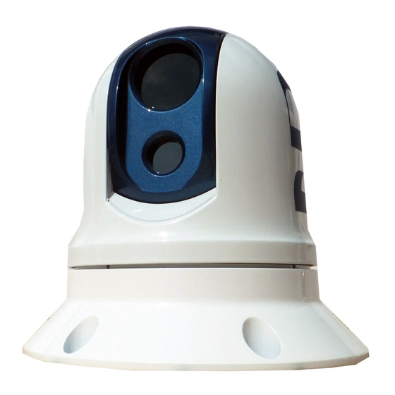
6.01 Hardware Installation Inner Dome Get to know your NightRunner! Contains the thermal camera The different parts of your camera are labelled here: module and tilt motor Protective Cowling Shields the Inner Dome and Tilt Daylight Camera Lens Window Pivot points Protective lens window for daylight camera. - Page 11 6.01 Hardware Installation (Continued...) 1. Once youʼve established a suitable installation position, offer the camera in to place and mark of the six fixing holes. Alternatively, use the drilling template supplied to mark of the fixing positions and cable entry hole. 2.
-
Page 12: Breakout Balun
6.02 Breakout Balun The 60ft CAT5 cable from your NightRunner terminates in the supplied Breakout Balun thatʼs pictured below. Power Supply 2.1mm DC Barrel Connector. Input from Camera CAT5 (B) RJ45 Connector RS485 Data Wires Connect to your IRIS595 Controller or other control option. -
Page 13: Powering Up
8.05 System Presets make and model. Third party control methods may differ from Iris controllers. For details of compatible third party control Certain functions of the camera that are not defined by the interfaces please contact Iris Innovations. Control of extended Pelco-D Protocol are called by using Presets. -
Page 14: Auto-Standby Feature
With all thermal imaging cameras, if the thermal scene is flat (ie, similar temperature), the image may not appear as sharp as it could be. With Irisʼs ICE™ feature enabled, each pixel is analyzed and where there are distinct differences in pixel colour, the cameras processor accentuates the contrast in order to provide a much more defined and clearer image. -
Page 15: Protocol Command List
The table below lists features specific to IRIS295 Series (NightRunner) Cameras that are not covered by the standard Pelco-D protocol and the commands that have been mapped in IRIS camera software to operate those features. Values are shown in hexadecimal. The checksum for all Pelco-D commands is the 8 bit (modulo 256) sum of the payload bytes (bytes 2 ~ 6) within the message. -
Page 16: Hardware Image Flip
10.02 Hardware Image Flip As well as storing the cameras address, the DIP switches in the base of the camera also control the camera orientation. Switch 8 on bank S1 should always be set to ON. This enables the camera orientation memory so that on bootup, the camera will always revert to the last position stored in memory. -
Page 17: Address Table
The cameras unique device address is set using DIP switch Bank 1. The following table lists switch positions for each address from 0~38. There are a total of 255 address positions available. For address settings above 38 please contact Iris Innovations technical support. - Page 18 Daylight: ON Gain Control Thermal: Automatic Daylight: Automatic Serial Data Connection RS485 / Pelco-D (Extended Features Accessed via Iris Variant) RS485 / Pelco-D (Extended Features Accessed via Iris Variant) Shock and Vibration IEC60945 MIL STD 810E IEC60945 MIL STD 810E...
- Page 19 DIP SWITCH SETTINGS Its vitally important to ensure the DIP switch settings for your camera are correct. Incorrect settings could result in issues such as video loss or no control. When you open the DIP switch window, hold the camera so the switches are orientated as shown below. Switch Bank 1 The top bank of switches is Switch Bank 1 and controls the video format (switch 3) and image flip (switch 8).
- Page 20 If the supplied cable is not long enough, contact your Iris dealer for information on our cable extension kits. If you need to shorten the cable, please ensure the correct termination polarity is observed as shown below. Remember, NightRunner has a Straight-Thru CAT5 568B cable.
- Page 21 APPENDIX: B CABLING (Continued): Typical Connection Examples Camera: IRIS295 /395 NightRunner Example 1: Single Camera / Controller This is the most typical setup, where a single NightRunner Camera is controlled by an IRIS595 Controller. The camera cable (CAT5) plugs into the RJ45 socket of the breakout balun. Then take the video output to your monitor, dvr or switcher, connect camera power to a +12 or 24VDC source* and connect the data wires to the IRIS595 data wires accordingly:...
- Page 22 If additional control devices are required, it is possible to daisy chain expanders to acheive the desired amount of inputs. Contact Iris for further details. Note: If you want to control cameras / matrices using a DVR or Web Server, these must be connected as inputs.
- Page 23 NOTES V3.00 Iss 05-06 18 - 23...
- Page 24 United States of America Tel: +1 (954) 533 9381 email: info@boat-cameras.com web: www.boat-cameras.com ©2018 Iris Innovations Limited. All information correct at time of going to press. Specifications are subject to change without prior notice. E&OE V3.00 Iss 05-06 18 - 24...
Need help?
Do you have a question about the NIghtRunner IRIS295V2 and is the answer not in the manual?
Questions and answers